Can’t make this thing ring,
Mark Johnson,
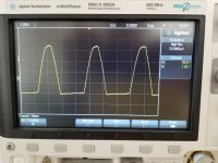
I tried, started out with a Stancor P-8715 filament transformer, 120V’s in nominal 6.3V’s out. I attached a basic 1N4004 rectifier and a 10R resistor in series, no capacitor. See the oscilloscope plot (photo) attached.
This thing is drawing over 1 amp. The top of the wave is squashed and distorted. I do not see a spike or ringing. I zoomed in to see the top of the Plot, no spike.
At this point I will continue to look but the snubbers can wait.
Thanks DT
Mark Johnson,
I tried, started out with a Stancor P-8715 filament transformer, 120V’s in nominal 6.3V’s out. I attached a basic 1N4004 rectifier and a 10R resistor in series, no capacitor. See the oscilloscope plot (photo) attached.
This thing is drawing over 1 amp. The top of the wave is squashed and distorted. I do not see a spike or ringing. I zoomed in to see the top of the Plot, no spike.
At this point I will continue to look but the snubbers can wait.
Thanks DT
Attachments
Why?transformer, ... nominal 6.3V’s out. I attached a basic 1N4004 rectifier and a 10R resistor in series, no capacitor.
Why do you think "no capacitor" is, in any way, representative of what happens in a linear power supply? How could anyone who owns an oscilloscope make such a colossal rookie mistake?
I recommend you abandon any pretense of experimentation, and instead fall back upon the unassailably true and obviously correct observation that many MANY super high end audio products over the years, which lots of people have loved to death, did not contain any mechanisms or circuitries to snub out transformer ringing. The Mark Levinson ML1? None. The Threshold 800A? None. The Audio Research SP-3? None. The Phase Linear 700? None. If nothing is good enough for them then it might be good enough for you too.
Hello Mark Johnson,
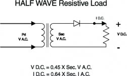
I went to the Hammond site and selected to wire up what they call “Half Wave Resistive load”; a transformer a diode and a resistor load. There was no intention to call this a linear power supply; add a couple of capacitors and maybe a inductor and we may call it a half wave rectifier with a Pi pre-filter.
I am a table top maker. I wanted to see real transformer / diode ringing on my bench. If anything should ring a “Half Wave Resistive load” should be it, especially using a 1N404 rectifier.
If including you in the conversation makes you angry I am sorry. I tip my hat, say thank you and I am on my way.
Thanks
DT
Attachments
The capacitor does, in fact, make a significant difference. Among other things, the current through the diode will be in short bursts when the voltage from the transformer exceeds the capacitor voltage plus the typical diode drop. It does not flow for a full half cycle as you would expect when the capacitor is absent. The short bursts of current to a fine job of exciting any ringing.
So far I am liking the M HPA results.
Hello,
I stopped playing around with the PS on the oscilloscope for now. I put a temporary heat sink on the M HPA and connected everything to the audio analyzer. The plots below are done with stuff sitting on the bench.
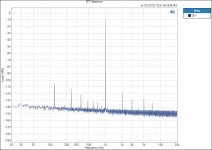
With the input shorted.
Noise 20 to 20k was 9.1uVrms.
See FFT plot below.
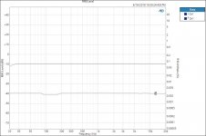
See THD+N and RMS level plot below. (there was no input, this is only noise)
With 80mVrms input:
See FFT plot below.
See THD+N and RMS level plot below.
Dead flat frequency response 25 to 20k
THD+N, 20 to 20k is 0.003% or better.
With 80mVrms input the output equals ~ 110dB’s at the output of my LCD2 headphones. The resistor at the amp output was 73R which matches the LCD2 headphones.
So far I am liking the M HPA results.
@ jhofland, thanks for the nod.
Thanks
DT
Hello,
I stopped playing around with the PS on the oscilloscope for now. I put a temporary heat sink on the M HPA and connected everything to the audio analyzer. The plots below are done with stuff sitting on the bench.
With the input shorted.
Noise 20 to 20k was 9.1uVrms.
See FFT plot below.
See THD+N and RMS level plot below. (there was no input, this is only noise)
With 80mVrms input:
See FFT plot below.
See THD+N and RMS level plot below.
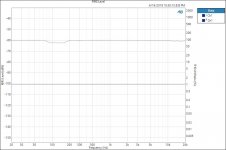
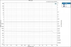
Dead flat frequency response 25 to 20k
THD+N, 20 to 20k is 0.003% or better.
With 80mVrms input the output equals ~ 110dB’s at the output of my LCD2 headphones. The resistor at the amp output was 73R which matches the LCD2 headphones.
So far I am liking the M HPA results.
@ jhofland, thanks for the nod.
Thanks
DT
Attachments
Hello,
This afternoon I took another look at this M HPA.
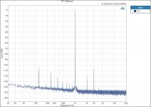
I adjusted the output to 1Vrms, that seems to be the standard here.
I adjusted the potentiometer on the PCB while watching the analyzer THD+N meter. The THD+N went down to 0.000954%. The Noise meter (20 to 20k, no weighting filter) went down to 7.6uVrms.
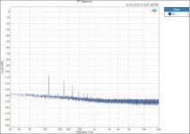
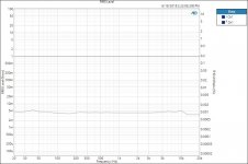
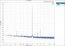
With the adjusted pot there are new FFT and sweep plots posted below. The 2nd harmonic fell to -122dBV, the 3rd Harmonic went up to ~107dBV. THD+N went down.
The power line harmonics 120hZ, 240hZ …. are curious to me. The transformer output center tap connects to the regulator board ground. The negative and positive outputs of the regulator are likely pretty close to clean. The ground connecting to the transformer output center tap is as likely as dirty as the dirt under my finger nails. (Next session I will look at this.)
Thanks
DT
This afternoon I took another look at this M HPA.
I adjusted the output to 1Vrms, that seems to be the standard here.
I adjusted the potentiometer on the PCB while watching the analyzer THD+N meter. The THD+N went down to 0.000954%. The Noise meter (20 to 20k, no weighting filter) went down to 7.6uVrms.
With the adjusted pot there are new FFT and sweep plots posted below. The 2nd harmonic fell to -122dBV, the 3rd Harmonic went up to ~107dBV. THD+N went down.
The power line harmonics 120hZ, 240hZ …. are curious to me. The transformer output center tap connects to the regulator board ground. The negative and positive outputs of the regulator are likely pretty close to clean. The ground connecting to the transformer output center tap is as likely as dirty as the dirt under my finger nails. (Next session I will look at this.)
Thanks
DT
Attachments
Last edited:
Big improvement to the PS harmonics
Hello,
This is the last of today's fun.
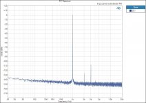
The last post I neglected to mention that the 5th and 7th harmonics disappeared.
I have rewired the power supply.
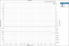
The PS now has two separate 14Vac windings supplying two separate full wave rectifiers; one each for the positive and negative voltage regulators.
The 20 to 20k noise has improved to 6.5uVrms.
The THD+N has improved to 0.00077%
There is a big improvement to the PS harmonics with the transformer secondary center tap removed from the ground.
Thanks
DT
Hello,
This is the last of today's fun.
The last post I neglected to mention that the 5th and 7th harmonics disappeared.
I have rewired the power supply.
The PS now has two separate 14Vac windings supplying two separate full wave rectifiers; one each for the positive and negative voltage regulators.
The 20 to 20k noise has improved to 6.5uVrms.
The THD+N has improved to 0.00077%
There is a big improvement to the PS harmonics with the transformer secondary center tap removed from the ground.
Thanks
DT
Attachments

Hello,
A little less noise with Gell Cell batteries supplying the regulator board.
The power line harmonics are gone.
Any comments to add?
Thanks
DT
Very nice results.
Don't let the simple circuit fool you. This is a very sophisticated design. I think I spent about $2000 on just the transistors to find the right combination of characteristics for this CFA topology. A topology I developed something like 45 years ago and it is still hard to beat.
Enjoy the music... tell us how it sounds, pls.
Nice work. Have you had time yet to listen to it? Can you describe the audible performance, please?
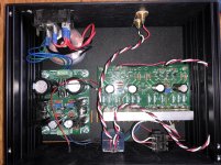
You do very nice work. Most of you guys do a lot better builds than I do. My mechanical build is awful in comparison.Finally got mine buttoned up and in a proper chassis today! 😀
THx-RNmarsh
Hello RNMarsh,
No, I have not yet connected a pair of headphones.
You have asked nicely a couple of times, I will do that. It will be after the 4th of July, there are a few things going on until then.
Thanks DT
No, I have not yet connected a pair of headphones.
You have asked nicely a couple of times, I will do that. It will be after the 4th of July, there are a few things going on until then.
Thanks DT
Well, another once again showed the THD is extremely low even when loaded with low Z phones. And, it was done without cascoding the jFET's and with minimal number of transistors and not using ultra high neg over-all feedback.
But how do you like an accurate amplifier? How does it sound with your headphones?
THx-Richard
But how do you like an accurate amplifier? How does it sound with your headphones?
THx-Richard
As was discussed before here - this HPA topology was created and first published in The Audio Amature magazine as an all bipolar circuit. This circuit -almost 40 years ago- the topology and design has not been significantly improved. Here are comments from that original article. The results for this HPA is same as the comments of the original iconic design.
View attachment RNM.pdf
THx-RNMarsh
View attachment RNM.pdf
THx-RNMarsh
As was discussed before here - this HPA topology was created and first published in The Audio Amature magazine as an all bipolar circuit. This circuit -almost 40 years ago- the topology and design has not been significantly improved. Here are comments from that original article. The results for this HPA is same as the comments of the original iconic design.
Thanks for sending this Mr. Marsh, much appreciated, "The Audio Amateur" magazine articles are hard to come by.
I'm ordering the 1970 issues on CD from cc-webshop.com but the rest don't seem to be available anywhere, even from cc-webshop.com.
Anyone know where I can get copies of them?
Cheers!
Rob
The article is in the 3/80 issues of Audio Amateur, so the 70s CD won't help you. If Richard say it's OK, I could scan my copy of that issue.I'm ordering the 1970 issues on CD from cc-webshop.com but the rest don't seem to be available anywhere, even from cc-webshop.com.
Anyone know where I can get copies of them?
Cheers!
Rob
---Gary
Go ahead and scan it t here or any where. I keep the copy rights to everything as part of agreement to publish. Same with linear audio pub.
If you have Linear Audio HPA article you can also copy it here with my permission.
THx-RNMarsh
If you have Linear Audio HPA article you can also copy it here with my permission.
THx-RNMarsh
The article is in the 3/80 issues of Audio Amateur, so the 70s CD won't help you. If Richard say it's OK, I could scan my copy of that issue.
---Gary
Go ahead and scan it t here or any where. I keep the copy rights to everything as part of agreement to publish. Same with linear audio pub.
If you have Linear Audio HPA article you can also copy it here with my permission.
THx-RNMarsh
Great, thanks guys, very generous of you both and much appreciated.

I'll still go ahead with the 1970s "The Audio Amateur" CD. And it anyone know where I can get the rest of TAA please let me know.
Cheers!
Rob
Go ahead and scan it here or anywhere. I keep the copyrights to everything as part of agreement to publish. Same with linear audio pub.
I've attached the article from Audio Amateur 3/80. It's a full function preamp including phono stage and line stage. The line stage is the predecessor to the headphone amp.
---Gary
Attachments
- Home
- Amplifiers
- Headphone Systems
- Marsh headphone amp from Linear Audio