I've just finished my first ACA 1.6 and I ran into a problem now. Maybe this was already answered but I really don't want to read 549 pages of posts, hoping the answer can be found somewhere. So I just ask the question.
When I turn on the amp, all seems good. There is a very small hiss through my 104 db speakers. However, when I turn on my pre-amplifier, I hear a very loud "hum/static". When I play music I actually hear it through the loud noise. The noise doesn't become louder when I increase the volume, the music does. Is this some kind of grounding problem?
Can somebody help me to identify and correct the problem?
Thank you
Faults like this are never easy at a distance. So to start the ball rolling... the first check (which you seem to have done) is to make sure the amp in isolation is quiet. That's a fundamental check it has to pass.
Your speakers at 104db are extremely efficient and will highlight any noise in the system. Have you used this preamp in combination with another power amp and found it OK ?
I don't know if the PSU supplied with the ACA actually has ground continuity from the DC output back to the wall socket. Some SMPS do, and some don't. Maybe someone can answer that. If there is continuity then a ground loop is possible depending on the partnering equipment.
Thanks for the reply.
Yes, I have used this preamp with other amps. Normally i use a Transcendent Sound SE-OTL and there was never a problem.
Yes, I have used this preamp with other amps. Normally i use a Transcendent Sound SE-OTL and there was never a problem.
While others help diagnosing build problems which are certainly beyond my skills, I could maybe help discarding obvious issues....However, when I turn on my pre-amplifier, I hear a very loud "hum/static"...
I had an issue with ground hum with mine when the PRE and the AMP were in different wall electrical sockets. Have you tried plugging in both the PRE and the AMP into the same power strip or regulator? That for me (they are both connected to the same inexpensive tripp lite voltage conditioner) solved the hum.
Of course there could be an underlying issue, but its a good place to start.
Best regards,
Rafa.
Thanks for the reply.
Yes, I have used this preamp with other amps. Normally i use a Transcendent Sound SE-OTL and there was never a problem.
The dreaded prospect of AC hum. You could have a look at this excellent article, courtesy of Dave Davenport, that's available close to home:
Audio Component Grounding and Interconnection
Word of caution, some of the links are dead so you might have to search for the references.
Jensen Transformers have a swag of info over at:
Jensen Transformers Application Notes | Jensen Transformers
The article AN006, Trouble Shooting Guide, by Bill Whitlock (who is often quoted and has published widely on the subject) should give you plenty to think about.
Hopefully it's a simple fix along the lines of Rafa's suggestion.
Last edited:
New Barrel Connector
I have assembled my newly arrived ACA 1.6, but I'm uncertain about one thing. In the picture attached the short white wire connects from the bare wire earth to a tab on the barrel connector. My new style barrel connector only has the top tab (for the bare wire earth) and the centre pin (to the power switch) - What does the short white wire attach to ?
I realize this a pretty basic question, but I fear the smoke.
Attachments
Mine arrived today after spending some time enjoying Frankfurt Airport ...
Have to head out of town for a few days but will start putting it together when I get back.
Have to head out of town for a few days but will start putting it together when I get back.
I've just finished my first ACA 1.6 and I ran into a problem now. Maybe this was already answered but I really don't want to read 549 pages of posts, hoping the answer can be found somewhere. So I just ask the question.
When I turn on the amp, all seems good. There is a very small hiss through my 104 db speakers. However, when I turn on my pre-amplifier, I hear a very loud "hum/static". When I play music I actually hear it through the loud noise. The noise doesn't become louder when I increase the volume, the music does. Is this some kind of grounding problem?
Can somebody help me to identify and correct the problem?
Thank you
There are a million things to try to correct this, and so many variables. I have 103db speakers and noticed a slight sound from the speakers. Normally I just look for the easiest and simple solutions to start. I crawled around and made sure electric wires and hardware like the meanwell power bricks... have some degree of separation or space from speaker wires and signal cables. Nothing crazy just a lil space. In my case moving the power bricks just a few inches away from the speaker cables and the problem went away. Not saying this is your fix, but try the simple solutions first and good luck!
Finished my ACA 1.6 a few days ago. It's an amazing kit! Thanks so much to those of you who are helping those like me get into DIY audio!
Thanks for the reply.
Yes, I have used this preamp with other amps. Normally i use a Transcendent Sound SE-OTL and there was never a problem.
And does the amp ground have direct continuity back to the ground pin of the mains plug ? In other words does a resistance check show close to zero ohms. Check that with nothing connected to the ACA inputs.
If it does, and if your preamp is the same (has continuity from its chassis to its mains plug ground) then you have a ground loop of some sort.
Correct!
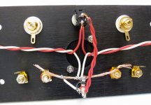
All grounds (PSU V-, XLR pin 1, and the RED speaker posts) connect to the single tab of the barrel connector.
The pin of the barrel is V+
Video -
YouTube
Image -

Sorry for another question. All grounds and the red speaker posts are then ground or negative. And then they are common. So then what is the polarity of the two black speaker connections. I could understand if the pictures showed All grounds connection to the black speaker posts as common. I guess I am missing how the two speaker outputs would be separate with the red speaker connections common. Not talking about the 24+ power. Thanks.
Last edited by a moderator:
Sorry for another question. All grounds and the red speaker posts are then ground or negative. And then they are common. So then what is the polarity of the two black speaker connections. I could understand if the pictures showed All grounds connection to the black speaker posts as common. I guess I am missing how the two speaker outputs would be separate with the red speaker connections common. Not talking about the 24+ power. Thanks.
The common (ground) connection is attached to the red speaker posts.
The actual output of the amplifier is connected to the black posts.
Because this amplifier circuit is inverting in absolute phase, if you connect your speakers to the amplifier red to red and black to black, absolute phase will be restored.
You are not the only one slightly confused by this, so it's totally worth explaining again. 😀
As always, do a DC voltage check at the various nodes. Something should show up and reveal a problem. Exact voltages will vary a little (and vary depending on where you have the bias set) but some major discrepancy should show if your FET's are cold.
(didn't you have this issue earlier and it mysteriously healed up ? and I suspected broken print somewhere)
Hi Mooly,
The previously good board with sound is the one that is not heating up. No power is coming to the circuit when I put the test probe to say, the middle lead of Q1.
All I did was remove the whole board and did a bit of re-soldering to where I see it needed. What a mistake.
As per the test points in the circuit you provided, I am not really sure where to place the probes.
I did some test and here they are:
R11 to either end of R10 = 4.32v
R11 to R10 = 4.31v
R9 across = 4.60v
R7 to Q3 =16.58v
On r1 and r2 anywhere I place the probes there is .33+v
Same is true with r3 and r4 with .43+v
I am not sure if above figures make sense.
Thank you very much.
Don't feel too bad; took me a while for that to sink in also. 😱Because this amplifier circuit is inverting in absolute phase, if you connect your speakers to the amplifier red to red and black to black, absolute phase will be restored.
Last edited:
So this is one of those things that is so simple that you may tend to overthink it:
the left channel output from the left channel board goes to the LEFT BLACK terminal
the right channel output from the right channel board goes to the RIGHT BLACK terminal
So the connections to the BLACK terminals are NOT common, one is connected to one board output, the other connected to the other board output.
The Red terminals ARE common to ground.
Basically DON'T: connect the output of each board to the red terminal on it's side of the chassis, and the blacks are common, which is what we normally do...
INSTEAD:
you connect the output of one board to the black terminal on that side, and you connect the output of the other board to the black terminal on the other side, and the reds are common,
Last edited:
I really think that your stand of refusing to add pictures when everyone has asked for them (and even pasted links to instructions on how to upload them freely to the server) is going to limit the amount of help people can give you and, quite frankly, limit your own chances of finding a quick and painless solution....All I did was remove the whole board and did a bit of re-soldering to where I see it needed. What a mistake...
Please, instead of investing more time into doing potentially more damage, invest time in posting some pictures so people can help you as your beautiful amp deserves! 🙁
Rafa.
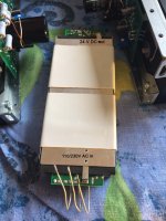
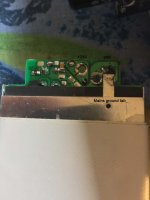
SMPS has the mains ground connected to 24V DC-out negative wire. Having in mind that the SMPS is an external "brick" to the amplifier, lifting the ground tab from the negative wire at the DC end should still preserve mains ground connection to the SMPS metal shield and heatsink to ensure safety is in place, while lifting the ground connection from the amplifier to break any ground loops. There's even a provision on the PCB to separate the two, but it is much easier just to lift the tab. It is worth a try...
Attachments
- Home
- Amplifiers
- Pass Labs
- Amp Camp Amp - ACA


