Howdy.
I bought: V18 PNP Sanken 2SA1216 JLH1969 class A power amp kit 10W+10W amplifier DIY L4-44

The kit came w/ nothing but the components and PCB.
My power supply is 15.3v AC.
Can anyone translate the following in to novice electronics English:
I bought: V18 PNP Sanken 2SA1216 JLH1969 class A power amp kit 10W+10W amplifier DIY L4-44
The kit came w/ nothing but the components and PCB.
My power supply is 15.3v AC.
Can anyone translate the following in to novice electronics English:
Code:
Debugging:
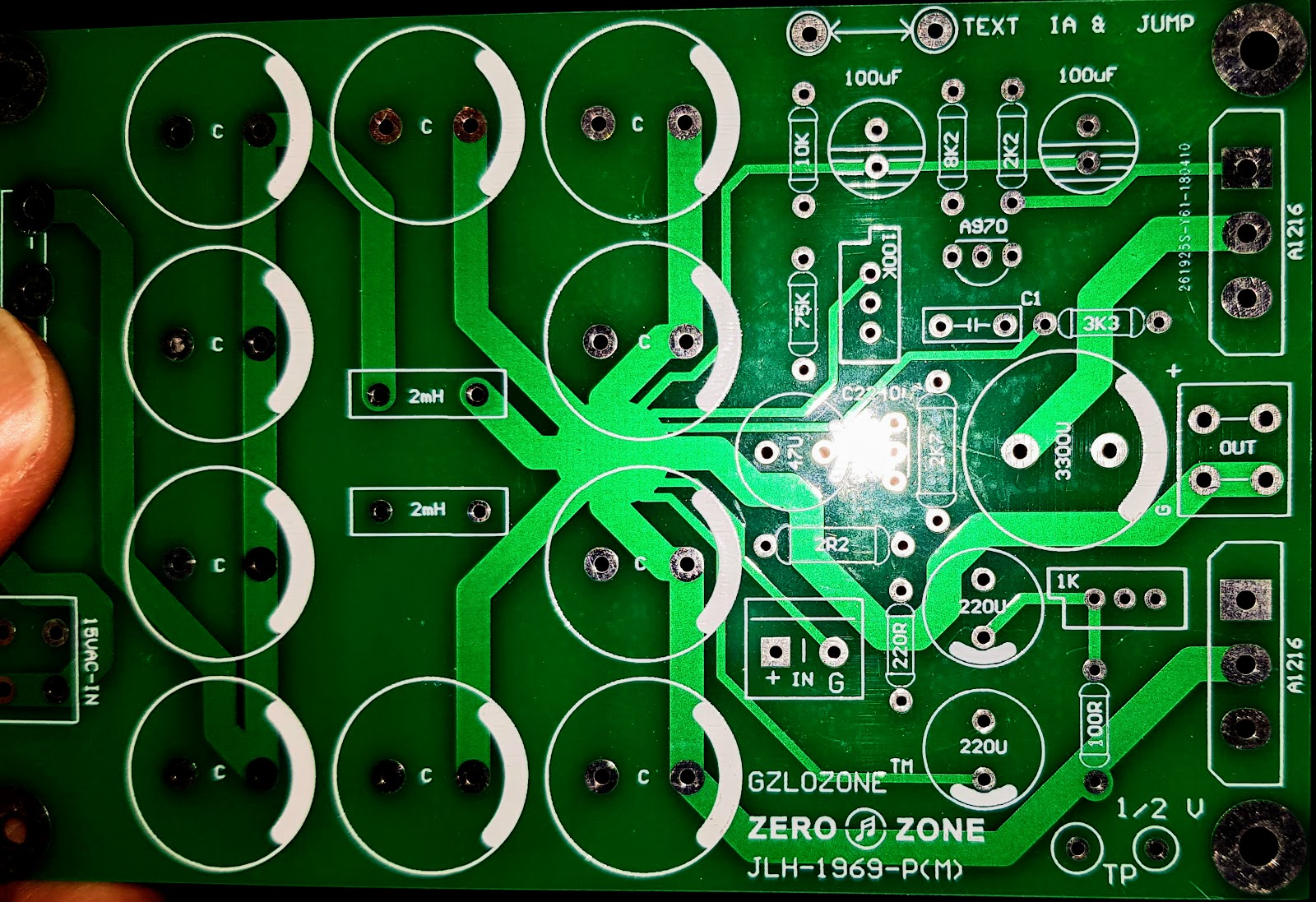
step1: first not connect the "TEXT" Jumper, and Series connect a Ammeter between this two point, adjust the "102" to make the Ammeter value about 1A.
step2: shorted the "TEXT" Jumper. test the "TEXT" jumper point to "GND" voltage as "V". then adjust the "104" to make the "TP" two point voltage
about 1/2 "V".It appears to mean that you connect a series ammeter between the points marked 'Text' and adjust the appropriate preset to give the recommended bias current.
Then remove the ammeter and link the 'Text' points together.
Now measure the voltage at the amplifier output (before the speaker coupling cap) and adjust to approximately one half of the DC supply voltage. It seems the points marked 'TP' are a convenient point to place your voltmeter.
Then remove the ammeter and link the 'Text' points together.
Now measure the voltage at the amplifier output (before the speaker coupling cap) and adjust to approximately one half of the DC supply voltage. It seems the points marked 'TP' are a convenient point to place your voltmeter.
Thanks @Mooly 🙂
Makes sense now.
Do I measure DC voltage directly from the D25XB60?
Also what happens to the sound if it's more or less than 1/2 that voltage?
Thanks again 🙂
Makes sense now.
Do I measure DC voltage directly from the D25XB60?
Also what happens to the sound if it's more or less than 1/2 that voltage?
Thanks again 🙂
From my reading, you first measure the voltage at the "TEXT" jumper to ground, which gives you V. Then change the voltmeter leads to TP (I assume the two points marked TP are that one is at the centre rail voltage and the other at ground, but you can check this by looking at the PCB tracks (check the underside of the board)). If they happen to be connected together (which I think unlikely) then you will need to measure between a TP and ground.
The reason to set the voltage at "dead centre" is to maximise the peak output power. If it is a little off, one half of the signal will clip before the other, causing distortion. At lower powers, a slight imbalance is not a problem.
The reason to set the voltage at "dead centre" is to maximise the peak output power. If it is a little off, one half of the signal will clip before the other, causing distortion. At lower powers, a slight imbalance is not a problem.
Thanks @Mooly 🙂
Makes sense now.
Do I measure DC voltage directly from the D25XB60?
Also what happens to the sound if it's more or less than 1/2 that voltage?
Thanks again 🙂
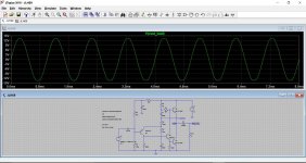
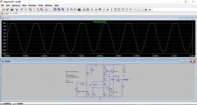
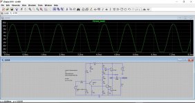
This shows what happens when the midpoint voltage is incorrect (this is on a 27vdc rail). First image is at around 13.5v, second image at 16.5v and third image at 11.5v.
You can see how it affects clipping and consequently the maximum available undistorted output voltage.
Attachments
Thanks john_ellis and Mooly, you guys rock!
The amp goes in to a 2.1 system using a miniDSP for active xover 80Hz and above go to a this amp, would you keep the voltage at exactly half?
I soldered all the components today; I want to make the board removable with interconnects... any recommendations for audio in and out also to the alps volume?
I have some JST, XT60, Deans and EC3... but should I be concerned about the EMI from the EI transformer in the middle?
Here 2 pic of my current amp... sounds really nice to me, but it is warm/tubey sounding... much more than my 300B tube amp.
All I'm doing is replacing the board, and cleaning up the volume PCB... is there anything else you think I shuld improve?
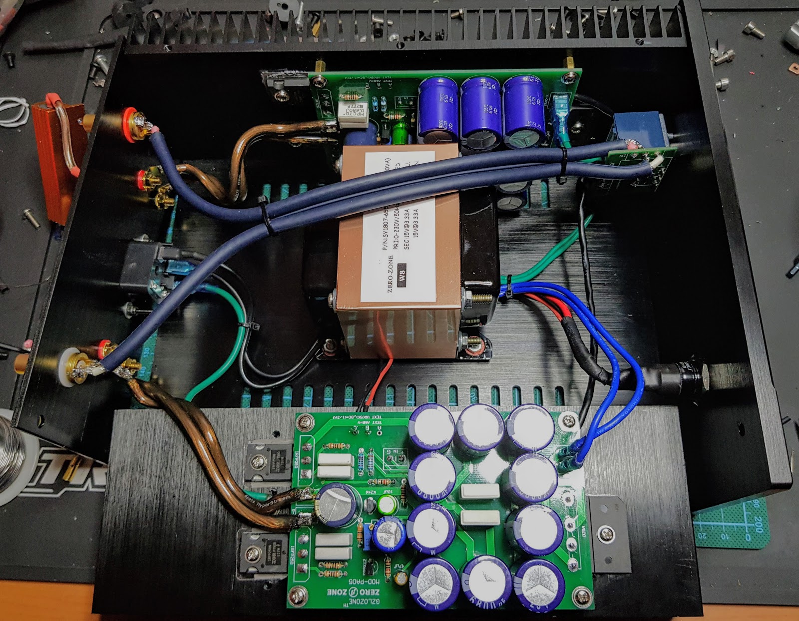
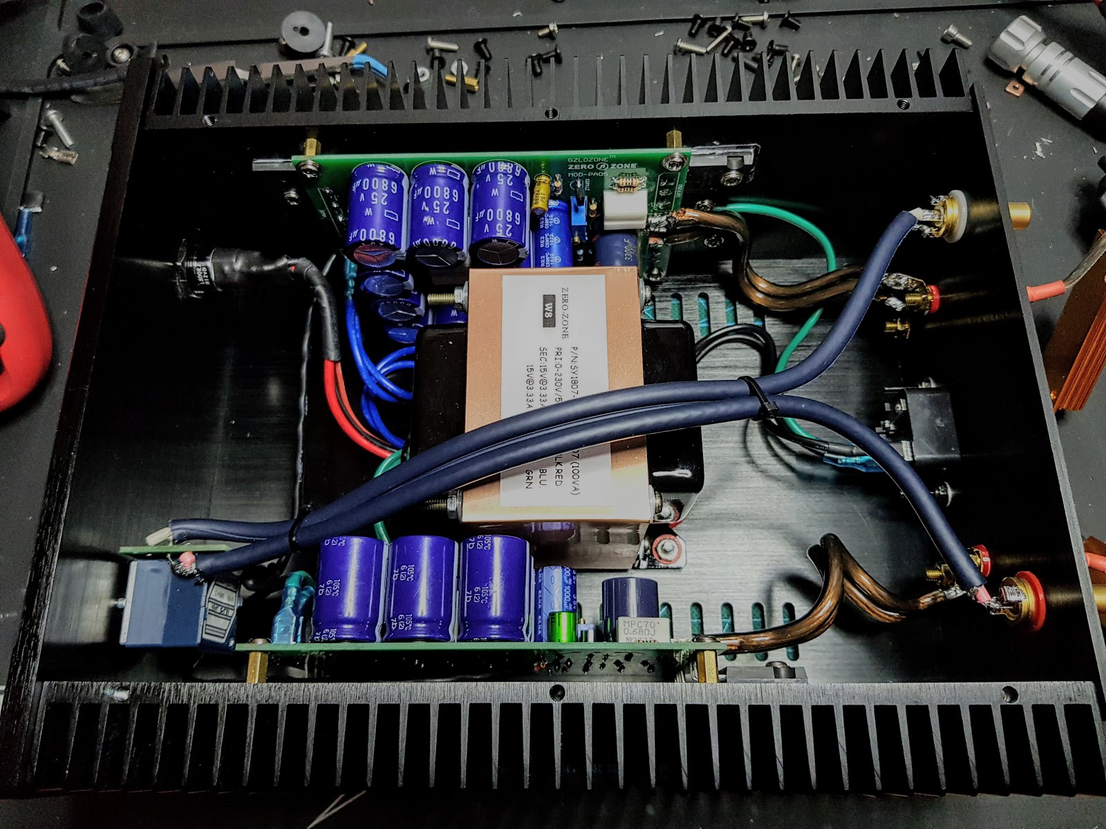
Thanks 🙂
The amp goes in to a 2.1 system using a miniDSP for active xover 80Hz and above go to a this amp, would you keep the voltage at exactly half?
I soldered all the components today; I want to make the board removable with interconnects... any recommendations for audio in and out also to the alps volume?
I have some JST, XT60, Deans and EC3... but should I be concerned about the EMI from the EI transformer in the middle?
Here 2 pic of my current amp... sounds really nice to me, but it is warm/tubey sounding... much more than my 300B tube amp.
All I'm doing is replacing the board, and cleaning up the volume PCB... is there anything else you think I shuld improve?
Thanks 🙂
Last edited:
I think I am right in saying the mid point also affects the standing current. Usually you have time to sort this out and if not your heat-sink is too small. It took me for ever to puzzle this out. The JLH is much like an over-biased class AB amp which will also use a centre voltage to set the standing current albeit 20 mA in AB. I did find my big heat-sink ( 0.25 degree / watt ) JLH mono-bloc was very stable on this and got there quickly. I don't think I noticed the supposed sharing of duties of the current sink 2N3055 and bottom half 2N3055 on sine wave testing. The current meter never changed, the load gave the correct wattage. Maybe someone would simulate this. My load was 8R on JLH 8R settings.
Nigel has raised some valid points. The JLH 69 design used resistors to feed the driver transistor and upper output device. The current flow in these resistors (two in series, one being bootstrapped with the capacitor connected to the mid-point) divides between the upper and lower output transistors. Since the current in these will vary with the voltage across them, that leads to the current in the output stage varying with centre rail voltage too.
The more important parameter to set first is the current, but to really ensure maximum performance, you would need to iterate between setting the current and then the voltage to fine-tune, and also at the working temperature since the current gain of BJT's is (slightly) temperature dependent. The effects are likely to be small, however.
(If you have two meters you can use both to set the conditions up efficiently.)
Nigel's other point about current sharing is interesting to explore. Old style design of output transistors (even epi 2N3055's) have a large non-linear response of gain (hfe) with current (Ic). The gain tended to peak at around 100-500mA, then fall with increasing (and decreasing) current. So the standing current had to be set such that the current in the load resistors allowed the OP transistors to pass the peak load current without being gain-limited. Suppose the base current needed to be 50mA for peak output. That is the current needed in the load resistors. Under no signal conditions, that means 25mA (approximately) would flow in each base, but at lower currents, the gain is higher so instead of being, say, 1A for a peak output of 2A, it would be more like 1.2A.
Modern transistors with a flatter gain with current characteristic are more ideal, so need less driver current and the quiescent current will be closer to 1A.
But for either type, the Class A nature of the design means that the two currents will be in opposite phases in the output transistors even though there is greater distortion in the older designs of device. Once again, the Class A nature largely counteracts the individual distortions, (in other words, the currents show considerable second harmonic distortion individually but as one is in opposite sign to the other they cancel) but the modern types will give lower overall distortion as the individual distortions are lower.
Last edited:
Thanks John. That's a very interesting answer.
I was very lazy doing my JLH. I set 2 x 100K to the first transistor base ( PNP ). I then added 10 K to one side then the other ( not both ) and watched the trend. It was close by doing that. I settled to about 0.5 V error. Once done using the 1969 original circuit and over sized heat sink it was rock solid. I used 2N3055 BC327/337-40. The BC337 was fine for many days and seems large enough. I had to add about 33 pF to the base collector of the BC337 as there was mild instability showing at 500 kHz to 2 MHz. I measured 160 kHz - 3 dB.
I got as good as 0.03% THD at 6 watts 10 kHz using 20 pence a piece 2N3055 of an Indian supplier. The problem is I doubt these 3055 are anything like the originals, mostly better I think.
Two things follow from that. As the speed of these 3055's is enough for a class A design we should only talk about gain linearity of the modern device. From what you say we might not see much advantage when using them due to cancellation of distortion. I also doubt from my own version that " better " transistors help. JLH in conversation with an admirer reported that some very fast devices sounded less good, ones about 6 MHz ideal. I could imagine the old BDY56 much loved by Naim Audio and ideal device. Cricklewood Electronics London have them if repairing smooth NAP160/250.
John. Simplistically said would that collector meets emitter in the JLH explain the cancellation best? I guess the upper device is the low impedance driver of the speaker. The collector has with the assistance of the current sink to push upwards. In a quasi complimentary design it is easier to see how this can work as due to local feedback the collector of that compound pair is at a low impedance. The JLH is actually very complex in how it works. I guess the drive splitter NPN is doing something of the same.
I must admit much of the JLH baffles me. The bits I do understand are the bootstrap driver to the NPN driver splitter. An ideal version of as class A injects very little nasties into the driver collector. I now can understand the output current as not very different to most modern class AB amps except higher current. Where is differs is that with class AB there is one near impossible setting of circa 20 mA, with class A it's perhaps 1 amp +/- 15% being fine.
One thing people never talk about is feeding signal into the feedback lower arm capacitor. This will reverse the speaker phase if trying. There are pluses and minuses. If you are using a NE5532(4) in your preamp low impedance can be driven. The Quad 303 has a very cunning way of getting the best from this idea which gives higher impedance. Commercially this makes very good sense. The output being out of phase with the input makes for better safety should wires get mixed up and speakers connected to inputs. Also the Quad 33/303 has remarkably few stages to do a very complex job. At no point does the Quad mismatch the stages impedance wise. However the 33/303 can sound very very poor if no trouble is taken to adjust input levels, however the Quad has options. Tape High suits CD ( I use mine via a switch-box for most modern stuff ). Radio 2 is highly unsuited to modern use. I used it with a modern op amp as very unusual phono stage. The sound quite remarkable. The point I am making is to experiment with designs common in the day and understand the good and the bad of it might give you results few get at any price. JLH's own preamps look ideal. Armstrong 600 series also ( like a better Quad type ). Done with care the simple stuff sounds more open and not unlike valves. Modern designs can sound detached and mechanical. Often this is due to not experimenting with op amp gain. Many op amps sound best at gain of 1 or > 10. I would consider using too much gain and and potting it down as an option. MC33078/79 can sound very good if gain of 2 is avoided. I have even used gain of 120 with one for an Ortofon SPU with spectacular results with the same hiss as one would usually get non transformer designs( - 60 dB or better ). To be frank most expensive op amps do not beat the MC33078/9 and it can do what NE5532 does in most cases. It has equal noise and distortion and 16 MHz rather than 10 MHz. In SMD it is cheaper than LM324N which is dreadful ( for engineering it's great ).
I see that the last 2 pics are of GZLOZONE's PLH style kit, rather than the JLH. It does seem to use Nelson's usual JFET/Mosfet lineup with a little BJT help to perform the phase splitting appropriately.
It would be interesting to know how close it is to Nelson's FET version. Is there a schematic suggested or referred to anywhere, raybies?
It would be interesting to know how close it is to Nelson's FET version. Is there a schematic suggested or referred to anywhere, raybies?
Nigel, you raise some more interesting points. In my constructions I've tried BC307 (now obsolete but pretty much the same as BC557) input and BD139 driver with epi 3055's and MJL3281A's. I had no stability problems with 3055 but needed 33pf across the f'b resistor with MJL's.
In simulations the old 3055 (RCA 1960's vintage), and in reality, was poor at 20kHz as its gain starts to fall, due to low fT, and with a limited base drive (unlike an AB with a driver transistor) nothing much can help it. The epi devices were better and MJL's the fastest. In reality I am sure there would not be much difference listening once 20kHz can be handled without loss of power, though the MJL's sounded good and to my ears slightly better if anything than 3055 (epi).
Regarding the output stage, the upper output device might look like an emitter follower but as it is current driven by the bootstrap (think high impedance) it is really only a gain stage. The output transistors therefore don't really offer a composite low+high impedance. The output pair together simply provide current gain with one acting in opposite phase to the other. So the output impedance is only controlled by the inherent OP impedance lowered by negative feedback as with most power amp circuits.
The way to think of the JLH is to consider each output transistor as a current amplifier. The driver transistor load resistors provide a constant current due to the bootstrap (which I must say is another feature of the design: the absence of emitter resistors means the bootstrap is quite effective) which splits two ways: part into the upper base and part through the driver transistor and (mostly) into the lower base. Any current which the upper transistor needs to turn on more (in a positive output swing (for the NPN Output verstion)) is sucked out of the bias resistors and that robs the lower base, so that transistor turns off. Conversely if the lower transistor needs more amps it sucks it through the driver transistor and robs the upper device. IN reality it is the signal controlling these currents, rather than the tail wagging the dog, but that is the gist of what happens.
I think the beauty of this design is what made it iconic, despite the shortcomings.
The distortion will be lower if the output transistors are more gain-linear, as the cancellation in the currents is not perfect. The upper output current is as you mentioned from an emitter but the lower is collector, so there is at least a base current offset difference.
The quad 303 is a bit of an odd design. The input is fed into a resistor to a transistor operating in virtual earth mode. Any input into the emitter of the input stage (instead of the base) will reverse the phase of any amp and will be much lower impedance, so unless your preamp has a low impedance drive, I would not recommend this approach. Besides, it may also change the frequency response and then may oscillate.
Last edited:
I see that the last 2 pics are of GZLOZONE's PLH style kit, rather than the JLH. It does seem to use Nelson's usual JFET/Mosfet lineup with a little BJT help to perform the phase splitting appropriately.
It would be interesting to know how close it is to Nelson's FET version. Is there a schematic suggested or referred to anywhere, raybies?
The schematic for my previous amp is attached.
I still haven't inserted the new JLH 1969 in to the chassis... I'll do it this weekend.
I have no idea about PLH or JLH, I just wanted to build a kit. With the Zero Zone I have 3 different amps I can build:
- V18 PNP Sanken 2SA1216 JLH1969
- X-one Mono Class AB MOS (power deficit but should work)
- PA-05 amp PASS ACA 5W; built already sounds good 🙂
Attachments
Last edited:
A friend Alan has gone back to teaching electronics at about 77. He says the majority of designs refer to other designs. Not so the JLH. I think there was a bit of luck with this design.
Someone said it is a typical valve like sound and the type of valve sound we should not like. From my measurements that's highly unlikely as the distortion was below the level where we might hear it and had very good harmornic structure looking like a suspension bridge curve. My example could maintain this at above 10 kHz.
Returning to Alan. He said to me in passing he never had confidence that low impedance due to loop negative feedback could work ( he has taught that for years ). I said I understood exactly what he meant. I would imagine the JLH to have more effective use of feedback in that the loop never is broken.

Well, there is something here to consider. First of all, negative feedback applied to a voltage output will reduce the output impedance (or raise the impedance if current output). So that is closed-loop output impedance. That can easily be demonstrated and calculated using simple feedback theory.
To simulate OL conditions, the classical approach is to split the feedback resistor into two: in the case of the JLH this means making the 2700 ohm 2480 and 220 (which mimics the feedback grounding resistor) then join the junction to ground with a large capacitor.
The D.C. conditions are identical to what they were. The A.C. mid-band conditions (audio band, 1kHz) are almost identical except for a minor difference is that the load (typically 8 ohms) is now shunted by 2480 ohms instead of 2700, (but excludes the emitter impedance of the PNP, which strictly speaking makes the classic approach invalid, however, the emitter impedance to ground (assuming a low impedance source) is in the order of 100 ohms, but in this case as the feedback resistor is shunted by an 8 ohm load makes this error small).
"Measuring" the output (in simulation) gives an open loop impedance of 15.5 ohms while the closed loop is 0.39 ohms for the two conditions I used (which is probably not a true comparison as the output voltages were different, but gives some idea of NFB).
However, as the small signal conditions inside the loop will be much the same for a given output current, the "loop output impedance" is going to be the same too. But the concept of a "loop output impedance" I suggest is somewhat nebulous as actual OP impedance has an effect on the sound.
The rather high OP impedance of the JLH might account for some differences in sound between speakers. It is due to the relatively low OLG which is due to the use of a rather high 220 ohm feedback "grounding" resistor.
Last edited:
The way to think of the JLH is to consider each output transistor as a current amplifier. The driver transistor load resistors provide a constant current due to the bootstrap (which I must say is another feature of the design: the absence of emitter resistors means the bootstrap is quite effective) which splits two ways: part into the upper base and part through the driver transistor and (mostly) into the lower base. Any current which the upper transistor needs to turn on more (in a positive output swing (for the NPN Output verstion)) is sucked out of the bias resistors and that robs the lower base, so that transistor turns off. Conversely if the lower transistor needs more amps it sucks it through the driver transistor and robs the upper device. IN reality it is the signal controlling these currents, rather than the tail wagging the dog, but that is the gist of what happens.
You can simplify and dumb down what happens if you look at the splitter+bottom out as a "drive-starved" darlington "VAS"; and the splitter+upper output as a single-bjt common emitter VAS with a EF added; and a nonlin "emitter degeneration" as it has the bottom output's BE junction to the gnd there. And there is the interplay, the gray area where you just need to somehow balance out the "split personality" of the both halves. It's a bit like dating two chicks ...
John.That's interesting. Even at 4 ohms it's quite good. Naim Audio used a real life 0R22 between amp and speaker. Not greatly different.
Thanks Anti. Well put. One of Douglas Self's amps are far eaisier to visualise.
I didn't see any evidence of current change using static signals. Just a simple mechanical meter on my bench PSU. It's not music so might not mean much. I don't think the amp was wrongly hooked up as output and distortion looked right as did standing current.
You can almost totally swamp this "high" fb resistor issue with closing the loop around the speaker (so around the output cap) and using a low-R resistor pair there - like 270R + 22R. This will make things different....
The rather high OP impedance of the JLH might account for some differences in sound between speakers. It is due to the relatively low OLG which is due to the use of a rather high 220 ohm feedback "grounding" resistor.
Then, there is the small cap that grounds the input pnp base (hf-cap). This one makes the said pnp a grounded-base amp at the freq where this cap "kicks in". So the whole OLG situation here is IMHO mainly the function of these two "opposing forces". This imho in a major way determines how you compensate and polish the circuit after-the-fact.
Valid imho for all simple "ring-of two imput" amps, class-a or ab, 0,5w or 50w...
My friend Alan 77 years old and electronics lecturer as I said finds the reality of negative feedback reducing ouput impedance hard to really understand even though he has always taught that it does. I know what he means. Here is an example of of observing it. If for argument a TDA2030 power op amp is DC coupled to a loudspeaker we can do two simple tests. Push the speaker in with the amplifier off, it will move quite easilly. Now again with the amplifier on, it will feel solid almost like a frozen coil that's damaged. The TDA2030 ( LM1875 etc ) is an example of a universal feedback amplifier and very like all modern amplifiers. Having never tried it with a JLH I can only assume it's the same despite the output capacitor. Being that it is a DC response it might be hard to say it's so obvious. I guess the quicker you push the more you feel it.
What this shows is that the output stage wishes to remain at 0V or whatever. As far as I can see this is a genuine example of what seems slightly impossible. That is the very high output impedance is made low.
One idea I played with was to give the JLH a gain of 2 and tune the stability as when an op amp ( NE5534 ). I could use 5 Vrms from the preamp and have a useful 2 watts from it should I wish. A class A booster to drive small smeakers and headphones whilst being very simple . Doubtless this would ruin the JLH, equally it might not. It would allow a high impedance inverting input and maybe a low impedance centre voltage setting for lower noise. The simplest stage would be an op amp driving a SE class A stage with current source. These often give 5 Vrms into 220R and nearly 2 Vrms into 32R without any heat sink.
Here is something that I put togehter in less than an hour to test theories. The transistors are over driven so a small metal heatsink required if using the same. BD135/139 could be used with a possible drop in performance. The green 2K4 resistor is to test a popular theory. It can be connected to the +Ve or -Ve terminal if trying it. It should sound slightly warmer if one way rather than the other. The less warm is possibly more accurate. With very high gain transistors it most likely is best with no green resistor. I am sure at least 10 improvements could be made to this idea. Using the inverting input is one. Ideally 10 uF would be polyester 100 V type, I used high grade 10uF 50V like Panasonic FC series.
Like the JLH it runs out of power into low loads if not set up for them. I found it to outperform the NE5532 which is noted for it's ability to drive low loads. Sharing the 1N4148 diodes was for fun. MC33078 would be my prefered op amp. The JLH is not unlike this set up when measured. Certainly not much worse. It makes my bloood boil when people say JLH not bad for it's day. It's excellent and that's the only truth worth saying. It might also save your ears from damage due to only having plenty of power.
Thanks for posting the schematic - that's certainly taken from Nelson Pass's. Briefly, the original 1969 JLH class A amplifier of this thread, is a minimal parts, 50 year old evergreen BJT design. The ACA was designed by Nelson Pass for DIY more recently, as was the PLH, his take on the JLH design. As ever, they are based on his distinctive trademark FETs.The schematic for my previous amp is attached.....
I have no idea about PLH or JLH, I just wanted to build a kit. With the Zero Zone I have 3 different amps I can build:
- V18 PNP Sanken 2SA1216 JLH1969
- X-one Mono Class AB MOS (power deficit but should work)
- PA-05 amp PASS ACA 5W; built already sounds good 🙂
There are ACA and PLH threads and much more at the the Passlabs forum that you might also be interested in. Here are the relevant Firstwatt design article links:
http://www.firstwatt.com/pdf/art_amp_camp_1.pdf
http://www.firstwatt.com/pdf/art_plh.pdf
- Home
- Amplifiers
- Solid State
- JLH 10 Watt class A amplifier