There is a manufacturing trick I recently saw on some China-made small output transformers that seems to work wery well. Appj uses it at least on smallest amplifiers. They start with a standard off the shelf PCB mount former with 16 lugs (8 per side) and central divider. This is the one you usually see on consumer electronics power supplies, RFI filters etc.
They interleave 4 windings on each section of the bobbin: primary-secondary-primary-secondary. The end of each winding is individually tied to one lug. They then connect in series the windings on the PCB. The 8 ohm output amplifier tap will use all 4 secondary sections, the 6 ohm tap will use only 3, and the 4 ohm will use two. When you use all 4 secondary sections, the result is good; on my amplifier is better than Hammond 125ASE. The manufacturing is likely automated because there is almost no difference to a conventional multiple outputs switching transformer and the result is cheap to manifacture; it is also fairly easy to rearrange the connections and change impedences. It would be an ideal transformer for small amplifiers.
They interleave 4 windings on each section of the bobbin: primary-secondary-primary-secondary. The end of each winding is individually tied to one lug. They then connect in series the windings on the PCB. The 8 ohm output amplifier tap will use all 4 secondary sections, the 6 ohm tap will use only 3, and the 4 ohm will use two. When you use all 4 secondary sections, the result is good; on my amplifier is better than Hammond 125ASE. The manufacturing is likely automated because there is almost no difference to a conventional multiple outputs switching transformer and the result is cheap to manifacture; it is also fairly easy to rearrange the connections and change impedences. It would be an ideal transformer for small amplifiers.
Attachments
Pat Turner was able to prepare OPTs where the intrinsic shunt capacitance and leakage inductance was well beyond the output stage response when valve Raa also comes in to the picture, and he just used horizontal interleaving. But any such high frequency response is not helped when using lower powered output stage valves with higher Raa.
Pat did use a messy two-pack varnish technique as the more practical diy alternative to a commercial bake-cool-epoxy vacuum impreg-overpressure impreg - bake process. That impreg process is a key aspect to stable reliable performance.
If the inherent transformer LC interaction, which Pat could typically push well beyond 100kHz, caused a noticeable resonance then that could typically be attenuated with a zobel set at a higher frequency where it just started to smooth out the first LC resonance, but otherwise had little interaction down at the amp response roll-off.
So I guess we may be looking for a solution when there is no fundamental problem (ie. in using horizontal interleaving).
IMHO, during the design process for a specific application the amount of interleaving, sectioning etc. should always be chosen to achieve best performance without having to add zobel networks. If the first self-resonance of the transformer is way above the roll-off with a specific power tube then the transformer is NOT optimised for that tube. When optimised the response should roll-off just before the resonance, hence even wider, with well behaved damping 0.5<Q<0.8.
There always is a best balance among shunt capacitance, leakage inductance and efficiency. Efficiency comes into play for the fact that the interleaving and sectioning can't go on forever as more and more insulation will eat space and if one makes an oversized transformer capacitance will be higher for the same scheme because it increases according to surface between layers. So oversizing will eventually lead to impractical size and weight.
Shunt capacitance is not easy to estimate but one gains some ability (practical formulas) after making a number of transformers. Instead leakage inductance is rather easy to estimate with very good accuracy and that should be the first indicator for making a good initial guess....
In the example you made then if one is happy with 100KHz could reduce the interleaving and/or sectioning and gain in efficiency. This also means less work and so cost saving...
They interleave 4 windings on each section of the bobbin: primary-secondary-primary-secondary.
That cannot be a good choice for quality transformer. It will have a lot more leakage in comparison to a symmetric geometry like 1/2secondary-primary-secondary-primary-1/2secondary for example.
Last edited:
so what is the differences between
Pi winding in this case is P,S,B,S,P(P=Pri S=Sec)sectioning and layers in horizontal across the E core
and traditional winding
P
S
B
S
P
in vertical across the E core
their magnetic field across the core should there have any differences in parastic capacitance and sounding?
Pi winding in this case is P,S,B,S,P(P=Pri S=Sec)sectioning and layers in horizontal across the E core
and traditional winding
P
S
B
S
P
in vertical across the E core
their magnetic field across the core should there have any differences in parastic capacitance and sounding?
That cannot be a good choice for quality transformer. It will have a lot more leakage in comparison to a symmetric geometry like 1/2secondary-primary-secondary-primary-1/2secondary for example.
sinc i start work on tubes never used ac transformer for output . buy core and winding myself .
That cannot be a good choice for quality transformer. It will have a lot more leakage in comparison to a symmetric geometry like 1/2secondary-primary-secondary-primary-1/2secondary for example.
would it be better to put the primary winding at the outer side of the bobbin,sec at the outer size of bobbin it is quite unusual.
Please enlighten me!
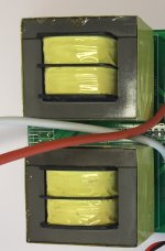
one of my photo didnt show up from my upload,here is the bobbin I so called new school winding bobbin(Matt BH is Pi winding bobbin)
Last edited:
Nothing "new school" about that. It is the standard way to get equal and well matched for DCR, leakage inductance and capacitance between each half of a push pull OT.
Patrick Turner has an excellent web site. He basically expands on the stuff in RDH4: output-trans-theory
RDH4: http://www.tubebooks.org/Books/intro_RDH4.pdf
Have a read🙂
Cheers
Matt
Patrick Turner has an excellent web site. He basically expands on the stuff in RDH4: output-trans-theory
RDH4: http://www.tubebooks.org/Books/intro_RDH4.pdf
Have a read🙂
Cheers
Matt
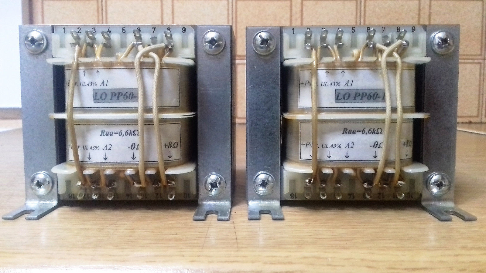
These transformers looks Ogonovski,one of my photo didnt show up from my upload,here is the bobbin I so called new school winding bobbin(Matt BH is Pi winding bobbin)
who made these?
would it be better to put the primary winding at the outer side of the bobbin,sec at the outer size of bobbin it is quite unusual.
Please enlighten me!
Both solutions are ok. I prefer to start and finish with primaries as I have always found this solution having less shunt capacitance. It could be related to how I make the transformer however Lundahl does start and finish with a secondary. You can have both primary or secondary as an outer winding. It is the distribution of the turns + windings and the symmetry that matters.
In the two cases above:
1) primary-secondary-primary-secondary
2) 1/2 prim.-sec.-prim.-sec.-1/2prim. (or 1/2sec-prim-sec-prim-1/2sec. like the Lundahls)
the average mmf (magnetomotive force) is the same however in case 2) is more evenly distributed than case 1).
So case 1) will have significant more leakage inductance.
The more windings the more evenly the mmf is. That's why leakage inductance decreases...
Last edited:
When optimised the response should roll-off just before the resonance, hence even wider, with well behaved damping 0.5<Q<0.8
While completely agreeing with you, I'm wondering if a higher Q (1-3) way above the audio band >100kHz is much detrimental to the sound quality?
Any twiddle in the gain phase near the gain or phase zero crossing in a GNF amp will have some influence on the stability character, and likely show up on a square wave response.
That may have only a benign influence in most situations, but could become an issue for quirky loads.
That may have only a benign influence in most situations, but could become an issue for quirky loads.
These transformers looks Ogonovski,
who made these?
these transformers are made by Ogonovski
with the GNF winding,are you saying that it helps to wider the bandwidth,how is it related to resonance?
While completely agreeing with you, I'm wondering if a higher Q (1-3) way above the audio band >100kHz is much detrimental to the sound quality?
No if you are not using global feedback but we are talking about tailored transformers and really isn't a great deal to get a well behaved transformer. If one buys a transformer off the shelf for general use then it is understandable and he has to deal with whatever he has got in hands.
Maplins sold an audio transformer. EI core with two bobbins. One for primary, and one for secondary. Two secondaries actually, but on that one secondary bobbin. It's odd to hear people say it wouldn't work. It was a 22-0 22-0 audio transformer, for their 50w amp boards. I'm actually selling one. Danbury made them. Who are about the only people still using that design when you need one.
I often pick up a Danbury and chop the secondary out to rewind it. They used to sell a few as kits, but now chopping them up is the only option. It gets me a 100VA core for £25
I often pick up a Danbury and chop the secondary out to rewind it. They used to sell a few as kits, but now chopping them up is the only option. It gets me a 100VA core for £25
It's not odd it's physics! The frequency response will be poor, in general.It's odd to hear people say it wouldn't work.
100VA core for £25
In fact that is a definition for power transformers.
You don't find it odd they would sell an audio transformer of this type, for their well known amp kits?
I buy the 100VA one's to rewind. It was 162VA. Though I expect a VA rating on all transformers for this duty. How else would you specify one
I buy the 100VA one's to rewind. It was 162VA. Though I expect a VA rating on all transformers for this duty. How else would you specify one
- Home
- Amplifiers
- Tubes / Valves
- old and new school of output transformer winding