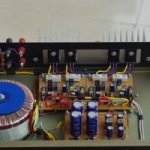
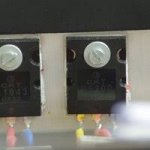
Hmmm... yes, I have been toying with this idea. The problem is that the PCB board is taller than the Heatsink, and there is no way to fit is rotated 90º....Why not mout the transistors with their contacts straight (or almost), so the board wil be perpendicular to the heatsinks? Then just use some L shaped pieces of metal to support the boards.
So, this would be the only viable placement options while still soldering the MOSFETS to the PCB:
Perpendicular:
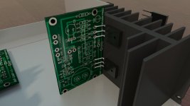
Parallel:
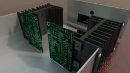
The perpendicular option is going to be hard as I cannot use the 'on board' heatsink wholes to secure the mosfets, and the box would need to be of odd shape as the heatsink would not fill the height of the Amp.
The parallel option on the other hand makes poorer use of the Heatsink, also has no 'built in' way of securing the MOSFETs, I would need to create some other form to hold them in place, and still I haven't overcome the 'PCB-taller-than-heatsink' issue, which would still require a weird box.
So I was hoping to go the route of cable-soldering the MOSFETs. Is that really not good for some technical reason that I would be better off with one of this much more complicated scenarios?
Thanks! Best regards,
Rafa.
Of course you can mount the MOSFETs off-board. Try to make the wires thick and as short as possible. Remove the 100 ohm gate stopper resistors from the board (put a wire link there instead) and solder them directly to the gate lead of the transistor. The drain lead will get hot, but that's no problem with sufficient heatsinks.
Friends, as I have mentioned, I have all the electronic parts for my project on hand (this requires a very warm and sound thank you!).
I now need to concentrate in the case and iron out some minor bumps in the road. As I have mentioned (probably in the build threads rather than here? but I could be wrong 😛 🙂 ) I cannot mount the PCBs to the Heatsinks, I need to separate them due to size and distribution of the heatsink.
So, I need to put the MOSFETs as 'satellites' of the PCBs, like this:
View attachment 686233
Is there anything important to keep in mind regarding this scenario? What gauge wire should be used? Will the actual legs of the MOSFET get hot? Is there an issue having them remotely attached? Do you forsee any issues? (I have the 1.1 PCBs so, as in the image, the Q1 and Q2 holes will be on a single side of the PCB).
Thanks for any feedback, best regards,
Rafa.
The constructions I have seen with Mosfets mounted external had the PCBs much closer to the heatsink so wires was only a few cm. Always best using short wires (then using about 1 mm2 wires should do it). Regarding the mount of the heatsink. It will be good to mount them so there is airflow up between the ribs. Your base plate blocks for this airflow.
How about lifting the Heatsinks from the base plate , maybe with spacers in order to accomaodate the PCB and give some airflow underneath the heatsinks as well. That is if you have not yet cut your side panels ... my2c
How about lifting the Heatsinks from the base plate , maybe with spacers in order to accomaodate the PCB and give some airflow underneath the heatsinks as well. That is if you have not yet cut your side panels ... my2c
Hello,
Easy to do with stand off.
Hiraga called it the chimney effect. In order for the heatsinks to work you must create airflow.
Greetings, Eduard
Thanks for all the feedback! Makes all the sense in the world!
So, with all the suggestions and what I may be able to do without becoming a mechanical engineer, how about this:
- I rise the heatsinks to allow for the PCBs Q solder points to be as close as the MOSFETs as possible, allowing for very, very short cables from the PCB to the MOSFET.
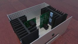
- This also allows air intake from beneath the the heatsinks (and outake from the perforated back / connectors panel (as shown in the previous image)
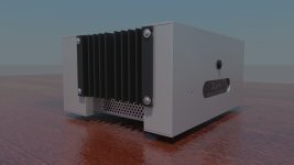
- What maybe wasn't clear in the first render is that the 'external' fins of the heatskink are 'free', they are not 'inside' the main body (the internal fins are, alas, unable to go outside the case)
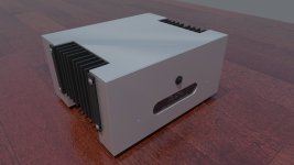
Does this sound like a better plan? Still, I can't figure a way to just solder those MOSFETS to the PCB and keep the design simple... but I am all ears to ideas! Thanks!!
Best regards,
Rafa.
So, with all the suggestions and what I may be able to do without becoming a mechanical engineer, how about this:
- I rise the heatsinks to allow for the PCBs Q solder points to be as close as the MOSFETs as possible, allowing for very, very short cables from the PCB to the MOSFET.

- This also allows air intake from beneath the the heatsinks (and outake from the perforated back / connectors panel (as shown in the previous image)

- What maybe wasn't clear in the first render is that the 'external' fins of the heatskink are 'free', they are not 'inside' the main body (the internal fins are, alas, unable to go outside the case)

Does this sound like a better plan? Still, I can't figure a way to just solder those MOSFETS to the PCB and keep the design simple... but I am all ears to ideas! Thanks!!
Best regards,
Rafa.
You could if you match the centre line of the heat sinks to the centre of the PWBs.
Mount the MosFets 90 degrees from the picture.
Then you have to have a small gap top and bottom for 'internal' air flow?
I like the idea for the chassis. Only thing I would do id mount the heat sinks inside the panel rather than outside, just neater?
Mount the MosFets 90 degrees from the picture.
Then you have to have a small gap top and bottom for 'internal' air flow?
I like the idea for the chassis. Only thing I would do id mount the heat sinks inside the panel rather than outside, just neater?
Last edited:
Hello,
The one in the lower position will heat up the other one. Maybe that could be a problem.
Greetings, Eduard
The one in the lower position will heat up the other one. Maybe that could be a problem.
Greetings, Eduard
Perhaps substitute Wood panels (of your preference) rather than those Ali thing/case sides. Not as if you need the room for Torroid / caps PS.
Thanks once more.
Alan, yes, that is the other approach I have been trying, the problem is there are two holes in the center of the heatsink (which are being used for the 'vertical' scenario).
If I am to solder to the PC Board, there are few combinations where the hole is not just-behind but off-centered to the MOSFET, which would be terrible for heat dissipation.
The one 'combo' that may work is something like this? But it will require high precision on everything, and I still need to find a way to secure the MOSFETs to the heatsink. But maybe its worth the try?:
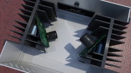
Eduard, yes, I am concerned about heat, and the Heatsinks are already 1.4W/C instead of the required 1W/C, so yes, I'm a little preoccupied about it.
Bare, considering the above, I was hoping that, by pairing parts of the heatsink to the aluminum panels, I would gain a bit extra heat dissipation. Perhaps I am being naive? Yes, maybe wood would be easier to work with. I'll look into it (the only wooden part I had considered for now was the front panel).
Edit: Oh, Alan, I think you are right about the heatsink inside, if I can work nice edges on the aluminum.
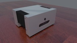
Alan, yes, that is the other approach I have been trying, the problem is there are two holes in the center of the heatsink (which are being used for the 'vertical' scenario).
If I am to solder to the PC Board, there are few combinations where the hole is not just-behind but off-centered to the MOSFET, which would be terrible for heat dissipation.
The one 'combo' that may work is something like this? But it will require high precision on everything, and I still need to find a way to secure the MOSFETs to the heatsink. But maybe its worth the try?:

Eduard, yes, I am concerned about heat, and the Heatsinks are already 1.4W/C instead of the required 1W/C, so yes, I'm a little preoccupied about it.
Bare, considering the above, I was hoping that, by pairing parts of the heatsink to the aluminum panels, I would gain a bit extra heat dissipation. Perhaps I am being naive? Yes, maybe wood would be easier to work with. I'll look into it (the only wooden part I had considered for now was the front panel).
Edit: Oh, Alan, I think you are right about the heatsink inside, if I can work nice edges on the aluminum.

Last edited:
Hahahaha... yeah, no, that won't work, sorry, the MOSFETs are rotated, the leg positions are wrong. Sorry, I will use my brain the next time I post something, I promise! 😛 🙂
There is one more thing to consider. The PCBs are not "mirrored" so difficult to make left and right channel 100% identical so components left and right gets exactly same temperature for best stereo image. If made as mono blocks you can make two 100% identical amps. Not a big issue......but I had it in my mind so I made two 100% identical mono blocks. E.g. in your design your output capacitors will not get the exact same temperature.....etc. In true high-end stuff issues like this is taken into consideration. But we can ask Pass if it would pass the requirements for a Pass amp 🙂
Well, I have always considered that, I'm not mirroring things: that is why you get a big capacitor on top for one channel and at the bottom for the other channel. But yes, Q1 would be above Q2 in one channel and bellow on the other. I kind of hate you a little bit right now! 🙂
But hey, isn't this true for the new ACA Amp Camp as well? You could argue that Q1 is at the back of the chassis for one channel and at the front for the other, so if air flow is not perfectly vertical, then you have the same issue? 😱
At any rate, I think that the MOSFETs are so close together, that they will share temps and that the heatsink would be dictating the temp most of the time, so I don't think that is too much of an issue, is it? (please, say no! 😱 )
Here are the correctly oriented MOSFETs:
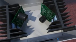
Do you guys think its worth pushing into this direction? How would you secure the mosfets to the heatsink? (other than drilling the heatsink which I am trying to avoid!)
Thanks!
Rafa.
But hey, isn't this true for the new ACA Amp Camp as well? You could argue that Q1 is at the back of the chassis for one channel and at the front for the other, so if air flow is not perfectly vertical, then you have the same issue? 😱
At any rate, I think that the MOSFETs are so close together, that they will share temps and that the heatsink would be dictating the temp most of the time, so I don't think that is too much of an issue, is it? (please, say no! 😱 )
Here are the correctly oriented MOSFETs:

Do you guys think its worth pushing into this direction? How would you secure the mosfets to the heatsink? (other than drilling the heatsink which I am trying to avoid!)
Thanks!
Rafa.
Mounting one PCB 'up' and the other 'down' will introduce no issues or problems in the proper operation of the amp. 😀
Well, I have always considered that, I'm not mirroring things: that is why you get a big capacitor on top for one channel and at the bottom for the other channel. But yes, Q1 would be above Q2 in one channel and bellow on the other. I kind of hate you a little bit right now! 🙂
But hey, isn't this true for the new ACA Amp Camp as well? You could argue that Q1 is at the back of the chassis for one channel and at the front for the other, so if air flow is not perfectly vertical, then you have the same issue? 😱
At any rate, I think that the MOSFETs are so close together, that they will share temps and that the heatsink would be dictating the temp most of the time, so I don't think that is too much of an issue, is it? (please, say no! 😱 )
Here are the correctly oriented MOSFETs:
View attachment 686404
Do you guys think its worth pushing into this direction? How would you secure the mosfets to the heatsink? (other than drilling the heatsink which I am trying to avoid!)
Thanks!
Rafa.
It is better to have considered it and then make an active choice. Theoretical the PCBs are not made for a stereo chassis. When mounting wires for input and output there are also wire lengths to consider…..if you want everything to be close to 100% identical. I sleep better if I know I have tried to make everything as good as possible. I find that the fun part of DIY.....also if it is only "academic".
Mounting one PCB 'up' and the other 'down' will introduce no issues or problems in the proper operation of the amp. 😀
Forgive my ignorance, but I'm having trouble understanding what the measurable / audible performance advantages would be to having the mirror imaged board layouts that MEPER has mentioned.
- Home
- Amplifiers
- Pass Labs
- Amp Camp Amp - ACA
