Yes, I know NFB will change a bit with volumen setting with passive preamp. But I have not noticed "mis behaviour" so far. I will compare using DAC as preamp. Also I use volumen setting at 3-4 o'clock and with 33k as input impedance for ACA so this also limits how much NFB will differ.
Will look at B1. Will need a preamp with a bit of gain.......
Will look at B1. Will need a preamp with a bit of gain.......
I will have a look at it. The coming preamp with Korg tube could also be fun.....I guess they will be sold out quickly when they show up in DIY shop.......
Very informative, especially the part on fixed vs variable output. Thank you!Yes, it is a Cambridge Dac Magic Plus. I am using the fixed output mode and go via a passiv "preamp". It sound good also when the DAC is in preamp mode but I always go back to fixed mode after a while. It sounds a bit better that way. In Preamp mode it will not give higher output. It can be turned up to the level it gives out in fixed output mode. I asked Cambridge how the volumen control was made. It is done in the DSP by multiplying the digital numbers by a factor (< 1) so some resolution are lost. It is done after up-sampling to 24/384 which helps a "bit".
The black box on top of it is a 12V linear PSU instead of the small smart phone adapter PSU. This upgrade improves the sound quality.
Here in Danmark the Dac Magic Plus has been on sale. Maybe a new model will come out soon. You may get one cheap. For the money it will be hard to find a better one.
Ok!
Now I have "adapted" and using the ACA with the DAC setup to "pre-amp" mode so I am sure ACA is working as it should. In pre-amp mode I have low output impedance vs. fixed mode where the 10k stepped attenuation is in between. Both setups seems to work fine.
Now I have "adapted" and using the ACA with the DAC setup to "pre-amp" mode so I am sure ACA is working as it should. In pre-amp mode I have low output impedance vs. fixed mode where the 10k stepped attenuation is in between. Both setups seems to work fine.
Hi everyone - first time poster here (and brand new to DIY).
I have a v1.6 amp on order and I'm wondering if it'll work with my current speakers, Audio Physic Sitaras.
http://www.audiophysic.de/download/sitara/sitara_hifinews_07_2009.pdf
My worry is that the amp's specs only mention 8 ohm impedence, but the Sitaras are 4 ohm. Will I potentially damage either the amp or the speakers by hooking them up together?
Thanks in advance for your input!
Greetings:
I have run car audio Blaupunkt TSc660 speakers with the ACA, which have a nominal 4ohm impedance, but they worked just fine. Why car audio speakers? It's what I had on hand. I built a pair of crappy MDF boxes to hold them and off I went. As always, your mileage may vary.
You can always get some small cheap speakers, some foam core and build your own enclosure. That's what I did (karlsonators). Tons of options from super cheap to scary expensive. Have fun, spend what you can afford to risk and learn from others here.
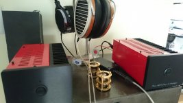
From time to time there has been some questions regarding using the ACA as a headphone amp?
Maybe the concept of the "converter box" I attached a picture of can be optimized for the ACA and the type of headphone used. The box as is works fine. It was made for small SE tube amps. It consist of 8.2 ohm load resistor and then a simple voltage divider over that load resistor for each channel. Tube amps like an ohmic load when operating. Maybe for the ACA a 16 ohm as load resistor will be fine....or maybe none at all. It can be chosen where ACA has the lowest distortion. The voltage divider is to adapt a reasonable sensitivity for the headphone and also for some safety not to have all the power to the headphone (ear damage etc.). Apart from that the box just converts from banana plugs to stereo headphone jack.
I can see…..not that much I got for the 100 dollars...….but manually work by people costs…..so some components, 1/2 hours of work…..etc....we end up there incl. tax and everything.
This should be a very simple DIY project 🙂
Could you tell the value of the two smaller resistors? Thank you.
Yes, there is a 56 ohm (green, blue, black) and a 220 ohm (red, red, brown). The signal to the jack is taken from the 56 ohm resistor.
The values can be optimized to the type of headphone used. E.g. the sensitivity of the headphone. But the values could be a good starting point. For the ACA I think the load resistor could be a 16 ohm.
The values can be optimized to the type of headphone used. E.g. the sensitivity of the headphone. But the values could be a good starting point. For the ACA I think the load resistor could be a 16 ohm.
You could run headphones directly from the outputs as well. A very early builder did that with great success, look a few months back.
I use 8+1.6 ohm resistors on output of aca to drive my headphones. You can do without it, but i like to have volume knob higher and some signal going through amp, not just barely above noise.
Audio Pages: Headphone amplifier
Audio Pages: Headphone amplifier
Is having some of the top cover screws not tightened down a Peter Belt level tweak about which we need to read white papers? 😉
Is having some of the top cover screws not tightened down a Peter Belt level tweak about which we need to read white papers? 😉
I noticed that if I unscrew all the screws from the, for example, a CD-transport top cover, the sound would change a lot... the change was even more obvious if I removed the cover completely. A breath of fresh air always helps...
I ran a first test with all the working JFETs on an unloaded ACA. It was connected directly between soundcard output and soundcard input, with no additional load on the output. Input level was -26dBFS, which translates to roughly 0.105VRMS, yielding around -3dBV at the output.
Power supply voltage was 20.75V, and the offset of the amp was adjusted for lowest THD reading for every individual JFET.
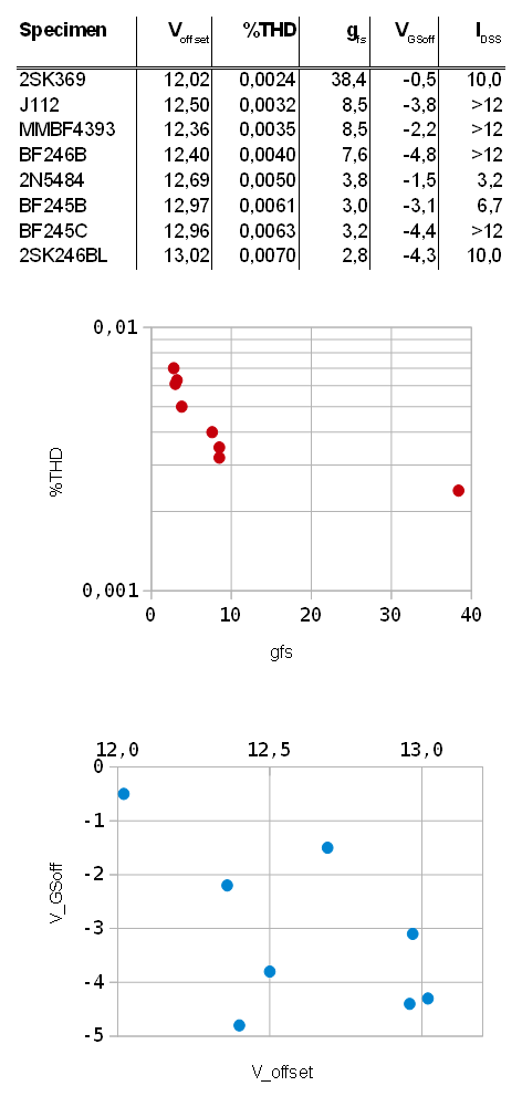
From the data above you can clearly state that the higher the transconductance of the JFET, the lower the THD.
Not as clear, but with a visible tendency, I would also state that the smaller the VGSoff of the JFET, the closer you can trim the offset voltage to half the supply voltage. This is important to maximize output swing in both directions.
So it looks like the 2SK369 is clearly the best performing part for the ACA, with the original 2SK170 being pretty close, I suppose. The MMBF4393 would be the runner-up (J112 too, with lowest possible VGSoff) and a cheap replacement. I got mine for 1/3rd of the price of the 2SK369.
I will probably get me some high wattage resistors to create a dummy load and test the amp while it delivers some more output power. Stay tuned 😉
Power supply voltage was 20.75V, and the offset of the amp was adjusted for lowest THD reading for every individual JFET.
From the data above you can clearly state that the higher the transconductance of the JFET, the lower the THD.
Not as clear, but with a visible tendency, I would also state that the smaller the VGSoff of the JFET, the closer you can trim the offset voltage to half the supply voltage. This is important to maximize output swing in both directions.
So it looks like the 2SK369 is clearly the best performing part for the ACA, with the original 2SK170 being pretty close, I suppose. The MMBF4393 would be the runner-up (J112 too, with lowest possible VGSoff) and a cheap replacement. I got mine for 1/3rd of the price of the 2SK369.
I will probably get me some high wattage resistors to create a dummy load and test the amp while it delivers some more output power. Stay tuned 😉
Attachments

Maybe I'm being thick, but where is the original 2SK170 in that chart?
Thanks!
Rafa.
Ps. I just received the parts for my ACÁ this Friday, so I'll start working on it as soon as I get everything regarding the build sorted out. Really excited!!!
Thanks!
Rafa.
Ps. I just received the parts for my ACÁ this Friday, so I'll start working on it as soon as I get everything regarding the build sorted out. Really excited!!!
It's not there because I don't own any 2SK170 and thus couldn't test it. The 2SK369 is basically the same as the 2SK170, but with double transconductance.
I ran a first test with all the working JFETs on an unloaded ACA. It was connected directly between soundcard output and soundcard input, with no additional load on the output. Input level was -26dBFS, which translates to roughly 0.105VRMS, yielding around -3dBV at the output.
Power supply voltage was 20.75V, and the offset of the amp was adjusted for lowest THD reading for every individual JFET.

From the data above you can clearly state that the higher the transconductance of the JFET, the lower the THD.
Not as clear, but with a visible tendency, I would also state that the smaller the VGSoff of the JFET, the closer you can trim the offset voltage to half the supply voltage. This is important to maximize output swing in both directions.
So it looks like the 2SK369 is clearly the best performing part for the ACA, with the original 2SK170 being pretty close, I suppose. The MMBF4393 would be the runner-up (J112 too, with lowest possible VGSoff) and a cheap replacement. I got mine for 1/3rd of the price of the 2SK369.
I will probably get me some high wattage resistors to create a dummy load and test the amp while it delivers some more output power. Stay tuned 😉
Nice!
I am looking forward to your further testing with an actual load.
I was wondering (if you have 2SK170), how would 2 of them connected in parallel compare to a single 2SK369... I know many prefer the 369 to 170, in MC pre-amp inputs...
Friends, as I have mentioned, I have all the electronic parts for my project on hand (this requires a very warm and sound thank you!).
I now need to concentrate in the case and iron out some minor bumps in the road. As I have mentioned (probably in the build threads rather than here? but I could be wrong 😛 🙂 ) I cannot mount the PCBs to the Heatsinks, I need to separate them due to size and distribution of the heatsink.
So, I need to put the MOSFETs as 'satellites' of the PCBs, like this:

Is there anything important to keep in mind regarding this scenario? What gauge wire should be used? Will the actual legs of the MOSFET get hot? Is there an issue having them remotely attached? Do you forsee any issues? (I have the 1.1 PCBs so, as in the image, the Q1 and Q2 holes will be on a single side of the PCB).
Thanks for any feedback, best regards,
Rafa.
I now need to concentrate in the case and iron out some minor bumps in the road. As I have mentioned (probably in the build threads rather than here? but I could be wrong 😛 🙂 ) I cannot mount the PCBs to the Heatsinks, I need to separate them due to size and distribution of the heatsink.
So, I need to put the MOSFETs as 'satellites' of the PCBs, like this:
Is there anything important to keep in mind regarding this scenario? What gauge wire should be used? Will the actual legs of the MOSFET get hot? Is there an issue having them remotely attached? Do you forsee any issues? (I have the 1.1 PCBs so, as in the image, the Q1 and Q2 holes will be on a single side of the PCB).
Thanks for any feedback, best regards,
Rafa.
- Home
- Amplifiers
- Pass Labs
- Amp Camp Amp - ACA