This is real 3 level.
using two triangle signals one above and one below zero, then I get 3 level including crossover🙁 and still doubling of the carrier. if is effective in split the 1 Khz singal in half, maybe overlap get soms help with bias, but it give the 3 level signal.
The other one I did also with same comparator outputs give also doubled carrier and has not that 3 level signal but 180 fase shifted signals, the inverter for mosfets are the cause of that, these has not trouble with crossover and no shoot through. quite low distortion with openloop.
maybe ltspice 64 bit is quite buggy
last pic I did try with IR2011 and mosfets, but what strange, I get very nice low distortion current over the 8 ohm load on top graph, but a very strange signal on the voltages on both sides of btl amp on low graph, maybe this get normal after soms more ms of sim, because this can be the cause.
regards
Attachments
Last edited:
Hi eva
Mine problem is not the topologies but to simulate it, I get strange results from 3 level, the fase shift do well, and give also nice results in open loop version, do you agree?, yes feedback is lower distortion I now, only I do not like it.
What concerns the tryouts, it is just learning, I have not yet plans, first the older projects, but mother needs still attention and go first afcouse, she is on better hand things go wel, so soon more time, now I sim for relaxing and learn some things..
Eva I want to go not in circels, however, I get not the results in ltspice, as I see it do not switch from null to rail and vice versa but switch from -rail to plus and vice versa, I miss the 0 reference in spice, maybe the comparator model is not oke.
see pic, I have done it as in the paper you send, excactly, and still it do not switch as in a real 3 level but is just fase shifted.
Thanks for the paper, I do have the crown schematics to look at. On topologies I did read a lot of stuff, so much attempts, and things to learn, calculations however I leave to the professionals from universities.
I have a nice paper from eindhoven did put it on try, nice stuff, low hd even with uge deadtimes. in zip the sim file.
https://www.google.com/url?sa=t&rct...573760-1.pdf&usg=AOvVaw06xi-RyZ7aYC8dAbjYufiv
So I go stop circulating and first start with 3 level. Am I have right the crown BCA amp is a fase shift version? using two buck circuits, doubling effective the carrier?. 3 level do also because it do sim like it, comparator setup is same as with 3 level, is this right? because for now, I get real three level only with two shifted carriers one for each half sinusoidal input. The shifted fase or BCA is quite oke for mine purpose, because the open loop did well here better as a normal setup, maibe because of deadtime.
Nice stuf.
Have a nice weekend. and thanks for help.
Attachments
Last edited:
I have to say high openloops do push music dead, as feedback mostly do, I did with a differential current feedback opamp and feedback it back for UCD, it did nice, also in high frequencies, 1 Khz and 20 Khz on pics, but yes it is sim.
Ok, I was busy to setup a two level carrier generator, but what is the best way, I did use two opamp buffers with dc level to the triangle opamp, so I can shift with offsets, it do work, maybe there are much better ways, now I can make multiply triangles for experimentation on 3 level and even higher, see last pic.
And now I go rest, and enjoy the sunday, because need to go in nature.
rgeads
Attachments

Last edited:
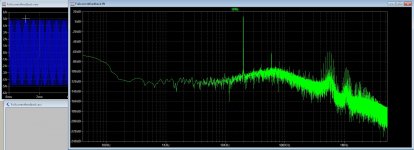
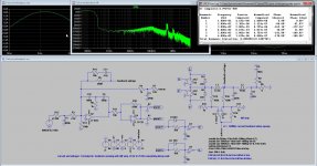
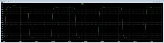
Some things done, a single class d with coil current/voltage feedback, I get quite low HD, from 20 Hz to 25 Khz it stays very low. see pics.
Because of the long time sumulationg for 20 Hz HD is higher, but in fact lower then with 100 Hz, HD go up if frequency rises but stays below -90dB.
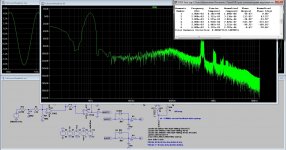
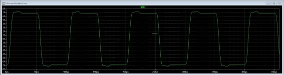
last pic with 100nS dead time, hd go up to 0.01 % the first three pics are squares of 1 Khz, 10 Khz 20Khz, and these looks oke also, you see the feedback allows quite fast responses, did use a diff opamp for both sides of the first demodulator coil, making combination of current/voltage feedback, I did use a video opamp for this.
regards
Because of the long time sumulationg for 20 Hz HD is higher, but in fact lower then with 100 Hz, HD go up if frequency rises but stays below -90dB.
last pic with 100nS dead time, hd go up to 0.01 % the first three pics are squares of 1 Khz, 10 Khz 20Khz, and these looks oke also, you see the feedback allows quite fast responses, did use a diff opamp for both sides of the first demodulator coil, making combination of current/voltage feedback, I did use a video opamp for this.
regards
Attachments

Last edited:
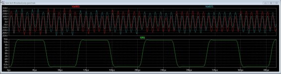
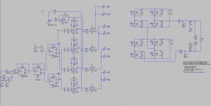
This full bridge fase shift one do also well, after some changes and tests, I think it is nice to build one soon, I get very curious about it now..
Still after some try I get not the 3 level switching and I do not now why, so need more study because I think ltspice does give that trouble or the ideal switches, maybe even the kind of comparators, need one for diff voltages?, or some offset setups.
some pics again, and now I think I have done enough for now, need to do also other things. Class D is quite interesting so I go on later.
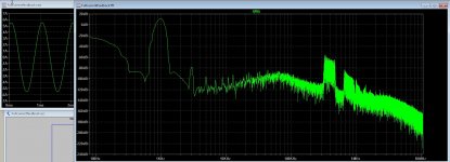
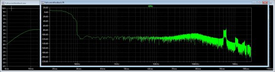
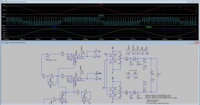
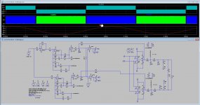
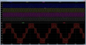
first pic, I do see strange signals whem measure on the both output voltages, common mode errors? because it happens with 3 level or faseshift. see the carrier doubled, it does very nice as predicted. the strange voltages are also very high, 280 volts !!, maybe @eva nows why? oke it is only the first 10 mS after that it disappair slowly. thanks. the current measurement over 8 ohms resistor give nice sinusoidal with ver low hd.
The square test is also very nice for a class d, reached after some changes and resims.
I have on the last pic setup a uge 120 ns dead time, see how wel it still does, for such a simple setup.
regards
Still after some try I get not the 3 level switching and I do not now why, so need more study because I think ltspice does give that trouble or the ideal switches, maybe even the kind of comparators, need one for diff voltages?, or some offset setups.
some pics again, and now I think I have done enough for now, need to do also other things. Class D is quite interesting so I go on later.
first pic, I do see strange signals whem measure on the both output voltages, common mode errors? because it happens with 3 level or faseshift. see the carrier doubled, it does very nice as predicted. the strange voltages are also very high, 280 volts !!, maybe @eva nows why? oke it is only the first 10 mS after that it disappair slowly. thanks. the current measurement over 8 ohms resistor give nice sinusoidal with ver low hd.
The square test is also very nice for a class d, reached after some changes and resims.
I have on the last pic setup a uge 120 ns dead time, see how wel it still does, for such a simple setup.
regards
Attachments

Last edited:
You are just discovering the pitfalls/deceptions implicit in some modulator schemes commonly in use.
- The paper advertising a company calling "class-BD" to "2-phase". Incidentally during last 10 years the aforementioned company lost most of its professional customers and was rescued by residential business. Now China is making a lot of pro-audio.
- The fact that these modulators (BD, phase shift) are almost unable to damp common-mode oscillation. You may get less ringing by adjusting some initial inductor currents and capacitor voltages, or coding a pair of simulated damping resistors to ground whose value increases with time. In general two class AD outputs are needed for a BTL capable of damping common-mode interference as well as differential-mode.
You are also getting closer to the design path I followed. Before investigating phase-shift self-oscillation in detail (10yr ago) I was doing triangle modulation with mixed voltage and current feedback, getting good results. I developed a sinewave inverter prototype that at low current used simple MCU-driven class BD modulation for low idle consumption, and at high current used analog triangle modulator with voltage/current feedback for removing output filter (LCLC) resonance. The design ended up being used as a low-impedance low-distortion AC generator for calibrating AC power meters.
Last edited:
Well eva, then I am om the right path right?.
you write The fact that these modulators (BD, phase shift) are almost unable to damp common-mode oscillation. You may get less ringing by adjusting some initial inductor currents and capacitor voltages,
So the fact that I get this strange oscillations is due to the kind of modulator/powerstage? ringing of low pass filter, thanks eva I go look at it..
I am started make a pcb for the hybrid ala only platefollowers, and the square produced is almost not possible wth class d, maybe the current feedbacked type do because of the width bandwidth these give.
I had placed some very low distortion pictures, if I make a self oscillating bd amp it do maybe better job I go look at it, I did see the errors do die out after some ms, but in sim this is afcause time consuming..
I try to design simpel as possible, al these opamps in the path do slam dead audio, feedback is a example. I have discovered after some reading that make a open loop class d supply ripple imuun is possible with a hysteric window who follow the ripple voltages, can reach -80dB suppression if resistors are matched 1 % types. als a extra opamp non inverting and feed in inverting input opamp get this effect, need feed forward comparator feedback making also a hysteric window, however hysteric windows make the comparator very non lineair, so mister disaster is always present, believe his name is Murphy.
pic is not class d but hybrid all plate drive, 20 Khz square, mucho better then in class d where the lowpass filter is the cause of that slow respons, fase trouble.. so a 5 level amp can be here mucho better.
Have a nice day, and I go outside because sun is back and I need sun.
Attachments
Last edited:
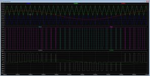
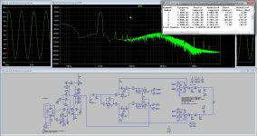
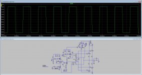
I put now some results.
this one do 3 level, just watch the schematics because I change it in every coming post for clarity.
here two triangles, out of fase, above and below zero transition, and one audio signal, open loop -40dB HD and no common mode ringing.
this one do 3 level, just watch the schematics because I change it in every coming post for clarity.
here two triangles, out of fase, above and below zero transition, and one audio signal, open loop -40dB HD and no common mode ringing.
Attachments
Last edited:
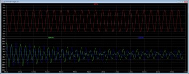
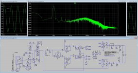
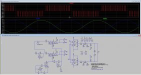
Same as above but now this one is with two audio signals one out of fase, and one triangle. HD -30dB open loop giving fase shift, (watch the switches here and between the posts).
Do not care the HD because it is from crossover, as the 3 levels has, can be easely cured by some electrics extra.
See the strange switching outputs, here is it what go not good in spice while all the books says it has to work such a way, and eva says the clarity of even the manufacturers is reason, and you right I guess.
Attachments
Last edited:
The real fase shift version, also watch how switches are connected, it is right that with separate triangles I get real 3 level and with one triangle and two audio signals one out of fase the fase shift version, here the books seems to be very unclear, you mention that before eva.
Now I have some more info I can at last decide what to do, the fase shift version looks most interesting because of the dead times and doubling of carrier frequency, also interesting maybe to fight common mode ringing is to use buck output like crown do, and more also do, time will tell.
Al these triangle driven versions has not a common mode problem, so good balanced.
Now the self oscillation versions, who has prefeedback afcourse.
regards
regards
regards
Attachments

Ahh I have succeed now with the ucd 3 level version, delay is the cause of things get wrong, I have to pay more attention on what I do setup in ltspice, forgot sometimes delete the old ones.
now I get crossover, but a delay on the last comparator buffers of 150 nS is a reason stuff overload, it is very delicate I do see in these 3 level amps, a triangle is maybe better.
I have to try to stay in one clock cycle on the zero passes then I have no crossover. but it is delicate, so maybe a help clock do work here sync things.
I am on track now, so I can go on where I was. thanks.
Attachments
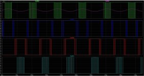
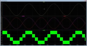
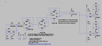
Now ready for the 5 level, the last one for investigate the results.
I have ready the four triangles 90 degree shifted with flip flops, with 5 level and 250Khz carrier it results x 4 is 1 mhz if it is right readed.
The result from 5 level pwm. Maybe schematic can better, I did need triangles with dc lift above and beneath zero level.
not yet the power stages and such, this looks interesting.
regards
Attachments

Last edited:
The 5 level, I have now simulated after have the switches right, that is a kind of puzzle.
I am not convinced that these multilevel types are a advance in class d, but the EMI is quite low and the switch stress low. different types of carrier generation is als possible, we need to balance the levels. the carrier is not doubled I do see on sim, but it dos four fold in 5 level, so did put a very smal filter with a 100Khz fall off it is still without ripple.
I have sim a casade version power stage with 8 mosfets open loop..
regards
Attachments

Last edited:
5 level this time fase shifted version, it do quadruple the carrier to 1.6 Mhz without stressing the switches who do work on 400 Khz so I can get quite low making good switch results. Also the voltages on switches are halved, and I just needs two single floating supplies. If this 5 level swither is usable for audio, I do not now, it is used for inverters, quite nice tough, making a sinusoidal output with high efficienty.
the HD is -60dB openloop on 4 ohm with 3600 watts of power. Common mode suppression is quite good, I have low pass setting on 100 Khz. EMI is also much lower then with normal class D technology.
However the parts count is some bigger, the need for 8 switching mosfets and 4 IR2010 chips, also I do not now if the charge pump do work with 5 level for the high side mosfets, then I need a extra supply line 15 volts higher then supply, but if i get a very nice amp, why not, mony is not real issue, high end is.
quite impressive, but yehh it is only simulation, however the working of the system is what counts and learn me some about this.
regards
Attachments
Last edited:
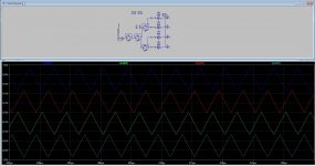
I need leveled triangles, I have done the following, using flipflops and a comparator to make a symetrical voltage and then connect the integrator, needs four, all on a different dc level, two below zero and two above zero.
can someone tip me how to do this best? need a good lineair triangle. is there not a integrator calculator on line? because calculation I am allergic for.
The use of the comparator was because I did want to get rid of capacitors on input integrator. I need four 500mV outputs.
Thanks.
regards
can someone tip me how to do this best? need a good lineair triangle. is there not a integrator calculator on line? because calculation I am allergic for.
The use of the comparator was because I did want to get rid of capacitors on input integrator. I need four 500mV outputs.
Thanks.
regards
Attachments
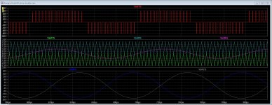
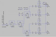
I have now I think did enough tests, as for outcome, a 5 level version is promissing with fase shifted triangles, I think we need not that much levels except when use it as a inverter for 220 volts or a high power amplifier for pa but implementing anyway do give a fourfold of the carrier frequency, 100 Khz become 400 Khz on output.
I do not now how Eva thinks about that but it is interesting.
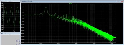
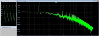
on pic's you see different triangle setups and one with comparator network on input, who did change the carrier doubling in sim, do not now what happens in real live.
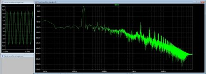
pic one offset triangles above and below zero, pic two 90 degree fase shifted triangles with no offset and comparator network, pic three without network both no offset.
regards
regards
I do not now how Eva thinks about that but it is interesting.
on pic's you see different triangle setups and one with comparator network on input, who did change the carrier doubling in sim, do not now what happens in real live.
pic one offset triangles above and below zero, pic two 90 degree fase shifted triangles with no offset and comparator network, pic three without network both no offset.
regards
regards
Attachments
Last edited:
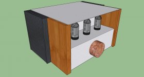
This is not class d but hybrid, just show a idea of a housing for it, just example, ideas welcome, it has three tubes but that can be more also.
I go made this all plate version, no feedback. but in meanwhile I do go on with
class D and circlotron, so work to do.
Working with sketchup is quite a pain in the, (fill the rest yourselfs).
regards
I go made this all plate version, no feedback. but in meanwhile I do go on with
class D and circlotron, so work to do.
Working with sketchup is quite a pain in the, (fill the rest yourselfs).
regards
Attachments
Last edited:
rees52, you know what, I strongly believe people like to have a motorized HiFi stuff. Look at Hollywood movies, yes some of them is quite silly, however, all show our future surrounded "transformers". The same thing commercial clips, if something is futuristic it's always mechanically transformed. So, if you have room enough, please try some mechtransform there.
rees52, you know what, I strongly believe people like to have a motorized HiFi stuff. Look at Hollywood movies, yes some of them is quite silly, however, all show our future surrounded "transformers". The same thing commercial clips, if something is futuristic it's always mechanically transformed. So, if you have room enough, please try some mechtransform there.
I do not now this will be needed in the high end sector, except maybe a motorized volume pot, because we need as less as possible in audio path, and for shure never a wifi kind of connections.
It is meant for using in high quality audio and these people like also simplicity because that is good for the sound.
thanks for tips.
- Home
- Amplifiers
- Class D
- Class D investigation.