yup
be sure that energy lines are thick and double sided , while gate and sense ( most right) can be eeny weeny
pull those source resistors up so you can make it less high ,and make it longer - if possible , better heat spread
be sure that energy lines are thick and double sided , while gate and sense ( most right) can be eeny weeny
pull those source resistors up so you can make it less high ,and make it longer - if possible , better heat spread
ZM, new capacitor and resistors arrived.
So completed amp 2 and powered up, still with 22k in R24 position.
Joy, joy, no issues.
Ran it up, adjusting all pots in steps.

Topped out at 460mV’s. So since it’s sitting on my work table, easy to play with, I went ahead and changed out R24 to 56k.
Cooking now, I’ve run it up to 500mV’s, temps haven’t stabilized yet, but after a half hour I’m up to 47degress. Amp door open, fan not running.
Thanks for all your help, so much more fun starting this one up!!!
So completed amp 2 and powered up, still with 22k in R24 position.
Joy, joy, no issues.
Ran it up, adjusting all pots in steps.
Topped out at 460mV’s. So since it’s sitting on my work table, easy to play with, I went ahead and changed out R24 to 56k.
Cooking now, I’ve run it up to 500mV’s, temps haven’t stabilized yet, but after a half hour I’m up to 47degress. Amp door open, fan not running.
Thanks for all your help, so much more fun starting this one up!!!

let us know how it sounds
while on bench , you can check Aleph AC gain
for that - run any Freq you know that your AC DVM can cope with (400-500Hz) , level - some round value on output - volt or so ; then simply measure AC voltage across source resistor of any lower positioned mosfet, write down; then measure AC voltage across source resistor of upper mosfet , write down.
then write here
🙂
Thanks ZM!
I went shopping on eBay last night and bought an inexpensive signal generator. Hope it works ok.

When I rebuilt/modified my SP10 turntable I had to buy an oscilloscope to adjust to spec.

I don’t really know how to use it, just read up enough to do what I needed for the TT project. But I really need to try and learn some more. Rebuilding my F5 Turbo v3’s are up next and this time I want to learn how to adjust P3. Would also like to read ripple on power supply etc and expand my learning.
I also bought some large resistors for 8 Ohm load and 4 Ohm load.
So I’ll probably have some more questions, sorry.
Later last night I left the amp running another hour or so after switching to the 56k resistors. Moved the temp probe to the screw holding a mosfet.

So the 56k resistor maxed out the pot at 508mV and 52.1c. Door open, no fans.
Should I go to 82k or 100k resistor, or should I play, listen, and test first?
play and listen
considering how easy you can change things , there is always time for that
btw. I forgot to say - for AC gain test , you need load on output
either dummy load or speaker , irrelevant , considering that level doesn't need to be high
considering how easy you can change things , there is always time for that
btw. I forgot to say - for AC gain test , you need load on output
either dummy load or speaker , irrelevant , considering that level doesn't need to be high
play and listen
considering how easy you can change things , there is always time for that
btw. I forgot to say - for AC gain test , you need load on output
either dummy load or speaker , irrelevant , considering that level doesn't need to be high
ZM, do you ever sleep? I really appreciate the time you take to make this hobby doable.
Easy you say! Stupid me built this overkill, I have to have help to get it up on the work table! But I understand what your saying. Plus I needed an excuse to stop and enjoy them for a bit!
Good thing I ordered up the large resistors. Going to make a chassis with two sets of binding posts, one set for the 1 Ohm resistors and one set, switchable, for 8 Ohm and 4 Ohm. The resistors are all 120W.
Probably take a good week to arrive, means a good week of playing HiFi!
sleep is overrated
I can dream awake
🙂
After a hard day of work, which included some time supervising here;

I switched in the 56k resistor into amp 1, rebiased/adjusted, and then brought them into the living room to run from my console project, which they will eventually be slid into. After running for about 3 hours here is the temp

I’d say pretty balanced! But man are they UGLY!! Good thing all you will be able to see eventually will be the back of the heat sinks.
BTW, sounds great. Although only using the built in JBL LE8T’s, they sound the best yet, even without the subs connected. This weekend I’ll bring out my Ekta Grande’s and crank them up.

I spent the day yesterday installing the amps into the console and made some shelf and equipment changes. Can’t believe it took the whole day, but everything turned out and fit like I planned.


I put the console up on a couple of moving dollies to be able to get behind it easier to final adjust and test the amps. This morning after a couple hours of warming up I readjusted everything and checked temps, still under 55 degrees.
I haven’t had time to really listen or connect the subs until late yesterday. I noticed a low hum in the subs so that made my put my ear to the main speakers, hum there too. I unplugged the subs, still hum, unplugged the pre from the amp and the hum went away.
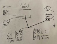
Here is how my grounding is set up;

Any ideas where to start looking?
I put the console up on a couple of moving dollies to be able to get behind it easier to final adjust and test the amps. This morning after a couple hours of warming up I readjusted everything and checked temps, still under 55 degrees.
I haven’t had time to really listen or connect the subs until late yesterday. I noticed a low hum in the subs so that made my put my ear to the main speakers, hum there too. I unplugged the subs, still hum, unplugged the pre from the amp and the hum went away.
Here is how my grounding is set up;
Any ideas where to start looking?
........
Any ideas where to start looking?
first thing I'm seeing is as attached ;
besides that , it is also important how power lines are routed on cap pcbs , but I presume you have good pcbs
when you short inputs and there is no hum , amp is sorted
you can also try is it better to connect NTC to PSU side , or directly to amp pcb GND
Attachments
Nice
May I ask what type of capacitors can be seen at first picture.
Gaborela thanks for the compliment.
Each mono block has 8ea of the Mundof’s and 4ea of the Rifa’s.


first thing I'm seeing is as attached ;
besides that , it is also important how power lines are routed on cap pcbs , but I presume you have good pcbs
when you short inputs and there is no hum , amp is sorted
you can also try is it better to connect NTC to PSU side , or directly to amp pcb GND
Thanks ZM!, I’ll try shorting the input first to see what happens.
I built up a rig to supply 1, 4, or 8 Ohm load with binding posts to start testing.

Can I ask where did you get the Mundorf's caps
I need 4PC of them but someplace they charge an arm and a leg. 🙂
Even 10000uF would be OK to me if the price is😱 not
Thank you
I’ve bought them at Sonic Craft and Parts ConneXion - The authority on Hi-Fi DIY parts and components before. I think they both charge an arm and a leg!!Can I ask where did you get the Mundorf's caps
I need 4PC of them but someplace they charge an arm and a leg. 🙂
Even 10000uF would be OK to me if the price is😱 not
Thank you
Finally sorted out the hum issue. The system is now 100% dead quiet. But took a bunch of turns trouble shooting. Clipply leads are a life saver!
I hadn't connected the tab on the XLR input previously, connecting it to the chassis ground dropped out about 50% of the hum. I moved the grounds around and around between the FE board, power supplies, and either side of the cl60/chassis ground. So below is what I ended up with. I’ve never seen anyone use 2ea cl60’s in their grounding scheme, but putting the FE board on its own cl60 dropped out the last 5-10% of the hum.
I know this probably means something, but everything is working and no hum, go figure.
Amps are sounding really good. I’m using some inexpensive balanced cables, so holding me back I’m sure. I’m in the process of getting some Transparent cables to match the rest of my system right now. And of course I’m just using the console LE8T full range drivers so far.
For sure I have plenty of power, clean, sound.
- Home
- Amplifiers
- Pass Labs
- About possible Babelfish J interest