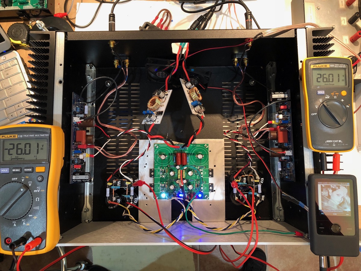
Here it is working and singing away at +/-26v rails and 1.3amps:
Here is a closeup of the Cap Mx:
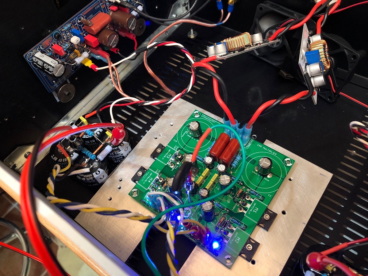
However, I am chasing a small ground loop that is causing the output to be 1.1mV instead of 0.1mV which is where I like it to be.
Here is a closeup of the Cap Mx:
However, I am chasing a small ground loop that is causing the output to be 1.1mV instead of 0.1mV which is where I like it to be.
Thanks for the advice Juma.
And sorry for posting that erroneous schematic. Didn't realize that I have posted the one with the IRF610. I have now deleted it from my computer. 😱
Greetings Skylar:
I saw (in another thread) that you had completed the Cap Multiplier you most recently mentioned in post 343 of this topic. It looked like you built it with point-to-point wiring, and I was wondering what components you ended up using, and how well it worked.
I have a simple SMPS (24v, pulling about 3.6A total for both channels of my ACA) with what appears to be some serious ripple (at least others are trying to get under 1mV RMS, and mine is over 5mV - although it appears most is in the 50kHz and above range). I like the power of the full 24 volts and am hoping not to have to lose 4v to the device. I'm running my ACA setup in a standard 2U chassis, and was looking to find a way to quiet the power supply. While I can't hear it on my present crappy (car audio based) speakers, I'm in the process of gathering parts for a set of .53x Karlsonator for a set of 3FE25 dirvers, similar to what you did.
Thanks for all the help (whether you knew it or not),
Ken
Greetings Skylar:
I saw (in another thread) that you had completed the Cap Multiplier you most recently mentioned in post 343 of this topic. It looked like you built it with point-to-point wiring, and I was wondering what components you ended up using, and how well it worked.
Hi Ken
Yes, I've built it point-to-point and used IRFP250's because they're cheaper and work just as well as IRFP240 in this role. The Mosfets are mounted to the bottom plate of the ACA enclosure.
My very limited understanding of a Cap Mx is that it will filter out ripple. But if it will get rid of all the ripple that you experience I can't tell you. From Wikipedia I've learned that the benefits of a Cap Mx are:I have a simple SMPS (24v, pulling about 3.6A total for both channels of my ACA) with what appears to be some serious ripple (at least others are trying to get under 1mV RMS, and mine is over 5mV - although it appears most is in the 50kHz and above range).
- A soft-start mechanism to slowly ramp up the current.
- It also provides a nice ripple reduction as a side benefit.
The main reason for me using a Cap Mx is to limit cross-talk between the two ACA channels which are powered from the same PSU, and it succeeds very well in doing that. My setup throws an excellent 3D bubble between the speakers, with the soundstage extending past the speaker positions.
There is a 4V drop, but I'm ok with 20V on the ACA's. However, I am considering a new preamp with gain. The current B1 buffer without gain is not adequate in the quieter passages of some tracks.I like the power of the full 24 volts and am hoping not to have to lose 4v to the device.
All I can say is my setup sounds awesome. The clarity and tightness of the 3FE25's is wonderful to experience. But be prepared to tame the highs with a baffle step. Good luck and let us know how it works out....I'm in the process of gathering parts for a set of .53x Karlsonator for a set of 3FE25 dirvers, similar to what you did.
Thanks for all the help (whether you knew it or not),
Ken
Christo
Attachments
Last edited:
Hi Ken
To get 24V out after the Cap Mx, you can use a Meanwell LRS-150-24 PSU which has a voltage adjustment range of 21.6 ~ 28.8V. It should also provide cleaner power with less ripple than your current SMPS.
That's what I intend doing soon. 😀
Christo
To get 24V out after the Cap Mx, you can use a Meanwell LRS-150-24 PSU which has a voltage adjustment range of 21.6 ~ 28.8V. It should also provide cleaner power with less ripple than your current SMPS.
That's what I intend doing soon. 😀
Christo
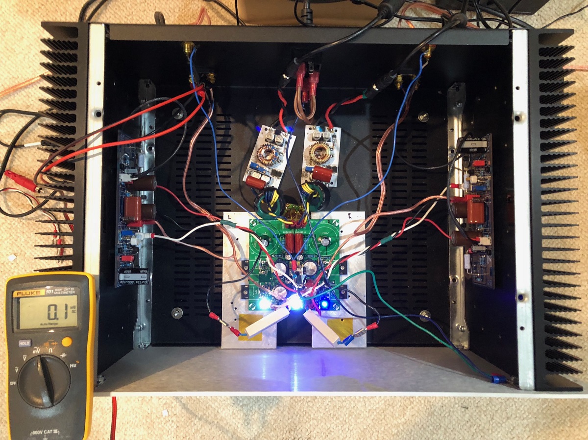
The noise and hum were all solved in the end. Needed a CMC between the DC-DC converter and the Cap Mx. Also added 10R between Cap Mx and GND of amp board. And GLB between clean ground at Star hub and earth/chassis.
http://www.diyaudio.com/forums/soli...rid-aleph-alpha-amplifier-43.html#post5345009
Noise is now 0.1mVrms at output with no music playing.
http://www.diyaudio.com/forums/soli...rid-aleph-alpha-amplifier-43.html#post5345009
Noise is now 0.1mVrms at output with no music playing.
Noise is now 0.1mVrms at output with no music playing.
How does one measure noise? With a DMM on speaker out?
.
X, what's the amps case you are using. I need one like that. Thanks.
Those are DIYA Store Dissipante 4U cases with 300mm UMS heatsinks. I wish the rear panels came precut with RCA, binding holes and IEC. If you want that, it becomes a $400+ deluxe case.
Dissipante 4U – diyAudio Store
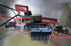
Done and done. Really nicely designed PCB, thanks Prasi! It was joy to solder up 🙂 except had some issues with my soldering tip, I guess it's time to buy new one. I didn't soldered IRFP's just yet.
This one will accompany Alpha20.
This one will accompany Alpha20.
Attachments

Last edited:
Done and done. Really nicely designed PCB, thanks Prasi! It was joy to solder up 🙂 except had some issues with my soldering tip, I guess it's time to buy new one. I didn't soldered IRFP's just yet.
This one will accompany Alpha20.
you are welcome. nicely done. All the best for your build of Alpha amp with this CMX.
regards
Prasi
Looking good Juntuin. What brand caps are those big red ones?
860010681031 Wurth Electronics | Mouser India
Hi Ken
To get 24V out after the Cap Mx, you can use a Meanwell LRS-150-24 PSU which has a voltage adjustment range of 21.6 ~ 28.8V. It should also provide cleaner power with less ripple than your current SMPS.
That's what I intend doing soon. 😀
Christo
Thanks Skylar. My SMPS (off-brand) will dial up to 28v (and probably beyond), I just didn't want to push it any harder than necessary.
Dropping 4v@1.7A - how big a hunk of aluminium did you bolt the MOSFETs to in order to dump that kind of heat? The constant current source in the ACA is dropping 12v@1.7A, and it's bolted to a huge heat sink...
Also, I remember seeing you had a post where you asked about changing the value of a component (the large value resistor). Did you? What was the final schematic & part list? Did you look into depletion mode options (2v drop, if I recall the post correctly)?
The notes I took show capacitance multiplier to be a 6 node system, so point-to-point should be easy enough to create, especially when the MOSFET has 3 of those points well supported.
------
To anyone paying attention -
What is the specific function of the diode? I've seen it across every pair of wires of a MOSFET (DG, DG & DS). I'm confused. I thought it was to keep the gate in a reasonable voltage range. Wouldn't a DS diode be some kind of snubber?
-----
fancy .sig file goes here...
ACA with cheap car speakers... working on upgrading!
Last edited:
P=IV
So P=1.7amp x 4v=7w
Not unmanageable but not nothing either.
Agreed. 7 watts in free air isn't that much. But this will be inside the chassis/box, and not able to shed heat as readily.
My concern was that my ACA uses a massive heat sink to dump exactly 6x that power (between the two MOSFETS, as I'm running a 24v power supply). That implies that I need a heat sink capable of 1/6 the same power dissipation (per channel). Presently, my heat sinks are overkill (300x80x40 disapante, .45 C/W - factory sinks were 200x80x40, .67 C/W for toasty hot fins). In theory, a 50x80x40 should do (remembering that the efficiency drops (number goes up) with the size drop), if it had the same airflow (which it would not). Since some people have built this, and are using it in similar application, I was wondering what they were using. Some of the photos give me a hint of two dimensions (LxW) of the aluminum plates most seem to be using, but no clue for the thickness, nor how warm it gets.
Theory is great, but practical experience provides far more valuable insight.
Can anyone who built this (for dropping 4v at about 1.5-2A) give feedback on what they used for a sink and how hot it gets? Did anybody build one an ACA? If so, can you provide a data point?
Thanks in advance to the best forum ever!
Dropping 4v@1.7A - how big a hunk of aluminium did you bolt the MOSFETs to in order to dump that kind of heat? The constant current source in the ACA is dropping 12v@1.7A, and it's bolted to a huge heat sink...
Also, I remember seeing you had a post where you asked about changing the value of a component (the large value resistor). Did you? What was the final schematic & part list? Did you look into depletion mode options (2v drop, if I recall the post correctly)?
The CMX Mosfets are bolted to the bottom plate of the enclosure which is 1.6mm thick. And the plate is bolted to 200x100x40 main heatsinks. The temperature of the Mosfets are the same as the ACA Mosfets: ~53°C, while the heatsinks measure 48°C on the outside.
No, I haven't had a chance to change the resistor to get faster ramp-up yet. My ACA's are out of commission until the enclosure is completed. The heatsinks and faceplate are about to be sent away to be anodized. I figured I'll do a proper job of the enclosure seeing that it's my first amp and also because it sounds so good. 😀
Ir's a bit more than that actually - 1.7A x 4.5v = 7.7W for each Q - there are 4 of them, so heat = approx 30w and if allowable temp rise about 25*C, the heatsink needs to be about 0.8*C/W in open air - so this will require a well-vented chassis or add a small fan
Perhaps it might be worth looking at another design of the pcb so the CMx transistor pairs could be mounted to each channel's main heatsinks next to the amp boards - not the simplest method, and adds more components. but it's one way to get around the 'excess heat problem' - the small Kuartlotron boards are quite easy to do this, for example, but they're only the final part of the supply
Or use transistors with lower voltage drop - we're not tied exclusively to the IRFPs
I mounted the heatsink with Prasi's completed board (with the same IRFPs) over the bottom panel vents but had to increase the heatsink size to about the 0.8*C/W size (just fitted it in!) and it has a temp rise about the 25*C with the well perforated top panel plus a 10mm gap next to the internal side of the heatsinks on the bottom panel for extra internal airflow (added cross bars to stiffen base panel - power transformer is now bolted to front plate) - it works quite well.
Hi James,
If the main heatsinks are big enough, then would mounting the MOSFETs on them and running wires to the CMX pcb be advisable?.
Regards
Prasi
If the main heatsinks are big enough, then would mounting the MOSFETs on them and running wires to the CMX pcb be advisable?.
Regards
Prasi
- Home
- Amplifiers
- Power Supplies
- Juma's Easy-Peasy Capacitance Multiplier