Ed, "you ignorant slut!" Scott is on to you, so you better wash that cap with holy water and force it to come clean! '-)
so you better wash that cap with holy water and force it to come clean! '-)
Or maybe just redesign the experiment so the results make sense.
Ed - I forgot >big smileys< here just trying to help. The trail of almost equal height harmonics is a big red flag and means time to subtract out the fundamentals and look at the residual in the time domain. The usual suspect is a discontinuity or glitch in the waveform smooth low order behavior can't do this. It's the old intellectual curiosity thing again, I can't help it.
I doubt there is any intermodulation. What I see are the 2 carriers , harmonics of the
20 Hz and maybe a little hum. Remember that the amplitude of IMD drops quickly
with the order, because high order IMD is made by mixing the low order IMD
again and again. Since IMD3 products are already weaker than the original carriers,
IMD5 products must be _much_ weaker than IMD3. I do not see anything like this.
When doing IMD / intercept point measurements I also found it absolutely necessary
to decouple the generators with attenuators _and_ bridges/directional couplers or the
output stages of the generators would happily intermodulate with themselves.
A common amplifier for the 2 signals is completely impossible, even when measuring
simple amplifiers. Normal signal generators @ 13 dBm_out do not have the level
to be combined after the attenuators and still deliver enough power for meaningful tests.
And such simple amplifiers are expected to be grossly nonlinear, not slightly like
passives that are linear in first order.
regards, Gerhard
It is DC in the coil. What do you expect ?The relay coil produced magnetic field is intimately close to the relay switch conductors and contacts.
What is the effect of relay coil stray magnetic field on signals passing through a typical relay ?.
Ditto permanent magnets in relays (bistable relays).
Ed, "you ignorant slut!" Scott is on to you, so you better wash that cap with holy water and force it to come clean! '-)
Yeah. JC has such a good solution, it's just that there is no problem in need of one.
Let us put bi-stable relay asideIt is DC in the coil. What do you expect ?
For the normal relay contacts and connected wires act like a transformer secondary winding. Primary winding is a relay coil. If coil current has a ripple, it will be transferred in contact network. Observed this for MC load relays :-(
Of course. But I wonder the level of this voltage ripple. Usually, it is a regulated 12V that we use. Let say some L7512. Ripple will be <30mV. The "transformer" ratio will be some 1/1000 with a lot of losses to add (very bad coupling) ? It will give something like less than 0.003mV (-110dB VS 1V) on my point of view. That can explain why I never noticed this on a power amp.Let us put bi-stable relay aside
For the normal relay contacts and connected wires act like a transformer secondary winding. Primary winding is a relay coil. If coil current has a ripple, it will be transferred in contact network. Observed this for MC load relays :-(
This said, in your example (MC) it can be a real problem because you refer-it to a very low level signal. I probably would not have thought of it at first sight.
Last edited:
In reed relays, the contacts are in the center with moving and fixed contact leads opposite each other. Here coupling will be the greatest.
In all of the other relays I have seen, the contacts are at the end with both leads coming from the same direction. See photo.
Any coupling into the fixed arm, will therefore cancel any coupling in the moving arm. Thus, coupling will be orders of magnitude less than in Tournesol's analysis.
In all of the other relays I have seen, the contacts are at the end with both leads coming from the same direction. See photo.
Any coupling into the fixed arm, will therefore cancel any coupling in the moving arm. Thus, coupling will be orders of magnitude less than in Tournesol's analysis.
Attachments
These are the only relays, that I could [quickly] find in the DigiKey catalog, dependable breaking more than 10A at 150Vdc (or higher), prices are 100 Euro's and up.
Electronic Components and Parts Search | DigiKey Electronics
In my opinion this is what you need to emergency-break an amplifier output.
It still is slow introduces many unwanted contact points in the amplifier output circuit.
http://omronfs.omron.com/en_US/ecb/products/pdf/en-g9eb.pdf
Contact resistance *1 30 mΩ max.
Contact voltage drop 0.1 V max. (for a carry current of 25 A)
Operate time 30 ms max.
Last edited:
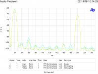
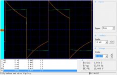
First image is the 1.8 uF Bennic capacitor into 10,000 ohms compared to the AP's output DC coupled and also using the internal AC coupling.
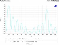
Second image is a not very good 2 uF capacitor with the same test waveforms. As capacitors with high Dielectric Absorption also have other faults it is difficult to isolate what factors cause the THD and IM distortions. At least one DA model has voltage dependent resistors.
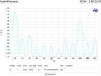
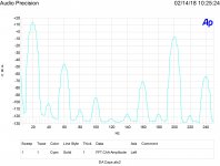
The last two images show results with no capacitor just nonlinear resistors.
Two ideas here. First is that DA does decrease sound quality. Second is the frequency where the impedance of a capacitor equals the load resistance will create the most IM distortion due to the exponential charging current deviation from a straight line.
Attachments
That last one is clearly showing off it's problems in a clear way. What was it Ed? Have you tried carbon composition resistors?
-Chris
-Chris
I have observed consumer integrated amps with LF cut switching causing a boomy/lumpy/resonant quality to the bass......Two ideas here. First is that DA does decrease sound quality. Second is the frequency where the impedance of a capacitor equals the load resistance will create the most IM distortion due to the exponential charging current deviation from a straight line.
Bad choice of series cap ?.
Dan.
EDIT: I have observed plenty of consumer integrated amps with LF cut switching causing a boomy/lumpy/resonant quality to the low/mid bass.
Bad choice of series cap ?.
Could be this! Phase shift changes amplitude and may be perceptible even without increased amplitude.
Yes, when LF cut filtered, sources containing lower fundamental impulsive (assymetric) sounds (kicks, toms, bass etc) suffer the most, losing bottoms that get replaced with an 'extra' that causes addition to/cancellation of the naturally occurring harmonics.
This changes the nature of the bass/mid bass and overall 'timbre', 'punch' and groove and feel, and sense of speed/tempo also.....the English PRATT.....just tweak the system series coupling caps values and types, duh.
Fully DC coupled system is of course generally impractical but going down to DC or very near to DC coupled system, especially the final stage power amp gives a comfortably settled and stable/solid quality to the overall sound....the nature/design and implementation of DC servos is critically important however.
DC coupling (and associated servos) combined with very low white noise and especially low 1/f noise is what JC is on about.
Dan.
Last edited:
As capacitors with high Dielectric Absorption also have other faults it is difficult to isolate what factors cause the THD and IM distortions. At least one DA model has voltage dependent resistors.
Without voltage/current variable capacitance and/or resistance (assuming no L's) there is no mechanism for distortion other than pathological issues. Victor, Samuel and others have identified several commercial caps that have no meaningful issues so why bother?
Last edited:
The Borbely all jet/fet dac, phono, line stage, and power amp are all direct coupled and use DC servos. Currently using the OPA 140 as a servo op amp (5nv/hz ), will test the AD 4625 - 3.3 nv next). MIT RTX 0.1 uf polystyrenes for the servo filter caps. The best Constellation audio, Pass, and Spectral products have very few, if any, coupling caps.
The power amp uses DC relay speaker protection and I added dc protection with shunt to ground relays to the preamps to keep the series relays to just the one in the power amp. Nothings failed ever requiring the protection to operate, except Jim Neighbors records.
The power amp uses DC relay speaker protection and I added dc protection with shunt to ground relays to the preamps to keep the series relays to just the one in the power amp. Nothings failed ever requiring the protection to operate, except Jim Neighbors records.
Last edited:
Without voltage/current variable capacitance and/or resistance (assuming no L's) there is no mechanism for distortion other than pathological issues. Victor, Samuel and others have identified several commercial caps that have no meaningful issues so why bother?
Don't think so. But you are welcome to ignore all the other issues. What is required in a sine wave oscillator just might be different than audio. THD is not the only issue.
Victor, Samuel and others have identified several commercial caps that have no meaningful issues so why bother?
Could I ask you to link to these discussions and/or mention these commercial cap options?
Not that I’ve done testing, but I’ve happy with the Vishay/Roederstein MKP1839, Wilma FKP and surplus military polystyrenes and micas to fill in the gaps. That covers most of the bases usually.
Curious to know of some other options / whats “reasonably good enough for those who want the highest possible reproduction beneath that which may result in mental health issues / forum addiction / 20k in analyzers / failed marriages while pursuing.”
Last edited:
- Status
- Not open for further replies.
- Home
- Member Areas
- The Lounge
- John Curl's Blowtorch preamplifier part II

