Dear Doug,
seen the great success with the two previous arms (ouch) I decided to do an encore: yet another string gadget, this time applied to a Birch.
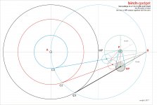
The chart you sent to Hiten had measures and angles, so I noticed that between the angle in P and that in B there seemed to be a constant relationship.
In my drawing the angles seem to be in ratio 1/3 (when the arm rotates 20° the pivot travels along the circle 60°) so with two pulleys and a belt (only two bearings, already present) we'll get a guide system linked to the rotation for free.
What do you think about it? no linear bearings or other devilries, no strange guides and other pivots: only torque forces and this time not working one against the other, hopefully. The friction bigger than in a Birch without a guide is only that of the belt, (with no motion).
According to your tests is there any hope that this mousetrap can move?
Seems too good to be true.
Ciao Carlo
How are your measurements going?
seen the great success with the two previous arms (ouch) I decided to do an encore: yet another string gadget, this time applied to a Birch.
The chart you sent to Hiten had measures and angles, so I noticed that between the angle in P and that in B there seemed to be a constant relationship.
In my drawing the angles seem to be in ratio 1/3 (when the arm rotates 20° the pivot travels along the circle 60°) so with two pulleys and a belt (only two bearings, already present) we'll get a guide system linked to the rotation for free.
What do you think about it? no linear bearings or other devilries, no strange guides and other pivots: only torque forces and this time not working one against the other, hopefully. The friction bigger than in a Birch without a guide is only that of the belt, (with no motion).
According to your tests is there any hope that this mousetrap can move?
Seems too good to be true.
Ciao Carlo
How are your measurements going?
Attachments
addendum
It is clear (Twice and others have shown this enough) that the Birch circle is only a useful approximation. Indispensable for diyers because an elliptical pulley or guide is impossible to be made on a lathe, even a chinese , already struggling to make round ones. Of course you could use the eccentricity (that comes out even if unwanted) but the mathematicians of this thread should do the calculations, and perhaps the eccentricity is so small that a diyer would not be able to realize it.
What I know from previous tests (Schroeder mentioned it as one of the merits of his solution) is that the guide must be elastic, otherwise at the first eccentric LP (do you have one that is not?) goodbye cartridge. So why complicate our life, problems are not lacking.
What I have discovered (better late than ever) is that there are infinite Birch circles: changig the diameter you can place it where needed.
Carlo
it seems that these Birch arms follow the 2nd law of Kepler, while CDs are simply going to garbage
Attachments
Carlo,
A final rabbit out of your hat for 2017. I like the horizontal possibilities. Vertical movement for warps, cuing, VTF and so on may be tricky. I hope you are seeing something I don't right now.
You are right about the multitude of Birch circles. Each choice is a different challenge, but, if built right, they all position the stylus better than a regular pivot.
The elliptical guide can be made by DIYers. They just have to think like metal smiths, not machinists.
I've been doing measurements and thinking about your experiments and Niffy's posts, but don't have anything to post yet.
I wish the best possible New Year for everybody.
Last edited:
Doug, unfortunately my rabbits are so lazy, refusing to move with only 200 milligrams!
So I ended up considering the Birch because you have studied them thoroughly even in practice, tracing even with low VTF. So there is a lot to copy, and very little to be invented.
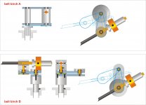
In fact, this arm is just a normal gimbal as you used (especially the solution A): but after reading of your troubles with various types of guides (including magnetic) i have only tried to change the driving mechanism: the bearings are already there to turn the arm, so the belt should not add too much friction (since it does not move); even the geometry does not seem outrageous to me. What do you think about it?
Carlo
an elliptic guide probably (better if bigger than that of LT), a small pulley without a CNC... (cnc are not fair means, in my diy ethic)
So I ended up considering the Birch because you have studied them thoroughly even in practice, tracing even with low VTF. So there is a lot to copy, and very little to be invented.
In fact, this arm is just a normal gimbal as you used (especially the solution A): but after reading of your troubles with various types of guides (including magnetic) i have only tried to change the driving mechanism: the bearings are already there to turn the arm, so the belt should not add too much friction (since it does not move); even the geometry does not seem outrageous to me. What do you think about it?
Carlo
an elliptic guide probably (better if bigger than that of LT), a small pulley without a CNC... (cnc are not fair means, in my diy ethic)
Attachments
Last edited:
What a dumb: the "crank" moves 60 ° but the moving pulley of 60 ° - 20 ° = 40 ° - So the ratio between fixed and mobile pulley is not 1/3 but 2/3 (40 ° / 60 ° or 60 ° / 90 °). Better, this is means less risk of belt slipping.
Tanti auguri a tutti per l'anno nuovo
carlo
Tanti auguri a tutti per l'anno nuovo
carlo
It took me a while, but I think I finally understand. The belt is a magic rabbit. It disappears Birch point B so it functions the same as the second arm on the two arm Birch, but isn't as difficult to build because only one set of pivot points has to be determined, an extra set of bearings is eliminated, and there is less horizontal mass. Brilliant. It will probably be easier to park on the TT than a Birch with point B. I really hope it works.
Looks very good, if you supply dimensions I can calculate the magnitudes for you.
Belt tension is going to be critical.
I hope it works, good luck & happy new year to you and all.
Belt tension is going to be critical.
I hope it works, good luck & happy new year to you and all.
Yes Doug, in fact I've started from your second arm: from what seen on my trials the crucial problem it's not geometry but guiding, that must be obtained from a force between 0 - 200 mg. Helm joints. forks and magnetic guide do not convince me and you too maybe, if you went to that clever idea.
Wha'ts good is that is one the very few solutions that really respect the rules of this thread: no sliding element, even in the guides, only pivoting ones. Perfect for chats, but we like to build tonearms, so here are some measures and some thoughts
measures
a thales circle equal to the platter (300mm) gives an angle of 30 ° from the outside to the spindle: this simplifies the calculations. With this measure we get an arm compatible with those of 9 ". if there is an adjustable base, SME like
considerations
As always on the arm act two forces - side force forces and stylus drag - With this kind of linkage the torque generated on the pulley from the side force depends on sine alpha (decreases from outer to the inner grooves) while that of the stylus drag with cosine alpha (increasing).
The worst position for moments of forces seem on outer grooves, if a mechanical CAD model could calculate values.... The system is more complicated than it seems-
The belt must be elastic, but not too much; better if flat: it is necessary that the diameters remain constant and to avoid any slipping. it could be even glued in one point.
Skating (the magic word of this thread): equal to every Birch no one excluded, even those with stellar co$$$$ts .
new Year's resolutions
Build this arm too, but first a mock up able to show every possible issue. After two tangential failures I would like to listen some good music and till now the only working arm I've derived from ideas on this thread (the first - wrong - drawing of the Schuch patent) is my 3Points: really good, but offtopic.
carlo
Thanks Twice, great help: i've attached a pdf, hoping it is importable
Attachments
Hi Carlo
I'm struggling to model this, the measurements in the pdf all seem to have been rounded.
I need an accurate A.P or C1.HP, a P.B will also help.
Thanks
I'm struggling to model this, the measurements in the pdf all seem to have been rounded.
I need an accurate A.P or C1.HP, a P.B will also help.
Thanks
Thanks Twice: working on this today, really I can't believe it ...
here is the drawing with the missing measurements, with 2 decimals - Sorry I use a graphic program, not a CAD
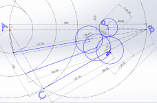
The geometry was built this way:
rT = rP = 150 mm (r Thales circle = r Platter)
B - C1 = sq root (2r sq - r sq) = 260mm
A - C1 = r
r Birch circle = 100mm
I moved the Birch circle along A-B until the angles coincide. First the one below and then up 3mm, to align the second.
Of course there is a small error avoidable with the ellipsis (the angles maybe follow kepler's law). The overhang error is about 2 mm, so I was thinking about an eccentric pulley - the mobile would be comfortable if it is 30mm, the fixed one i've calculated of 20 mm but I'm not completely sure because the movements are not two but three. 2 pulleys + crank
By imposing the necessary tangencies with these measurements A-HP is 223 mm and therefore an arm like type B could be easily mounted on any TT
Thanks again, and a happy new 2018 (I envy your season - here cold rainy days)
carlo
here is the drawing with the missing measurements, with 2 decimals - Sorry I use a graphic program, not a CAD
The geometry was built this way:
rT = rP = 150 mm (r Thales circle = r Platter)
B - C1 = sq root (2r sq - r sq) = 260mm
A - C1 = r
r Birch circle = 100mm
I moved the Birch circle along A-B until the angles coincide. First the one below and then up 3mm, to align the second.
Of course there is a small error avoidable with the ellipsis (the angles maybe follow kepler's law). The overhang error is about 2 mm, so I was thinking about an eccentric pulley - the mobile would be comfortable if it is 30mm, the fixed one i've calculated of 20 mm but I'm not completely sure because the movements are not two but three. 2 pulleys + crank
By imposing the necessary tangencies with these measurements A-HP is 223 mm and therefore an arm like type B could be easily mounted on any TT
Thanks again, and a happy new 2018 (I envy your season - here cold rainy days)
carlo
Attachments
Hi Carlo
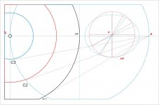
I tried my best to fit your dimensions, could not quite get there but very close.
All the black shapes are constrained to Birch, only the blue shapes can be moved and this allows to get least error on the tonearm length of which you have 2 choices.
Either the shortest C2=166.54 or C1+C3=167.54
C2 will give you a max underhang of 1mm at start and end of the record, with a +1.01 deg error off tangency.
C1+C3 will give you a max overhang of 1mm at the center of the record, with a -1.01 deg error off tangency.
Choose wisely 😀
Attachments


If you could somehow rotate the moving pivot by 180° but still keep the ratio between the pulleys near 2/3, then you will be able to reduce the error very close if not exactly to zero by offsetting the pivot point on the moving pulley by 1mm.
This will conveniently trace an ellipse.
I suspect with these dimensions though, the ratio is not exactly 2/3 anymore and needs looking at.
You would then probably have to use C1 as the length.
It looks like you might be on to something very promising here Carlo.
This will conveniently trace an ellipse.
I suspect with these dimensions though, the ratio is not exactly 2/3 anymore and needs looking at.
You would then probably have to use C1 as the length.
It looks like you might be on to something very promising here Carlo.
Great work Twice, thanks - more or less I had seen that the geometry was acceptable, but your investigation reassures me completely. Doug and you have knowledge and experience essential to try to achieve a true result together.
The problem remains that of the guide: here from my previous attempts and from the pendulum tests I understood two things
Tolerances - geometrically the guide should be rigid, but in this case the accuracy should be the width of a groove divided by the lever arm = few microns: clearly absurd, also because the disc has issues that would lead to skipping or worse. So the guide in practice must allow these movements and inaccuracies: not so easy.
Forces: here the thing is serious, maybe you will have noticed in my second arm - built on the hypothesis split plane + linear bearing - that even with a cart that moved with 100mg or less there was practically nothing left for driving (2 photos in response at icsaszaar show this well).
So - since the Doug or Schroeder Birch arms work - here it is necessary to understand if the moments of the forces applied on the pulley are correct. My feeling is that on the outer grooves we are very close to the crank deadlock and I do not know if the stylus drag, that here instead works well, is able to help.
Is it possible to draw the vectors at various points? (mobile and fixed pulley)
I think it can be reasonably applied to the stylus a drag of 2-3mN and 5- 6mN of side force.
Carlo
Pulley: eccentricity is just what I was thinking to use. I had seen the 2mm error of overhang, but I had also tried the ellipsis aligned on A-B (100x106mm) that gave a perfect coincidence of the angles. So I was, and am, uncertain about what to do.
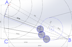
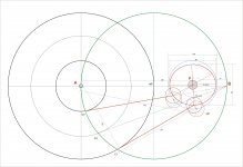
Here is a possible solution for you.
The Δ between ∠C1HP'P and ∠C3HP'P = 42.58° and ∠HP1P'HP3 = 62.61°
This ratio = 1:1.470408 and drives the pulley sizes of main pivot = 40.48mm and moving pivot = 59.52mm.
As the main pivot rotates CW by 62.61° the moving pivot has to rotate CCW by 42.58°.
A straight belt won't work, you would need to X the belts and it's not ideal but possible.
Another option would be to use an idler wheel moving pivot as below.
Rotating the moving pivot 180° will not be possible without complicated gearing, but it might be possible to reduce the error by ~1/4% by spreading the error across the whole playing area by offsetting the verticle pivot on the moving pivot. Might not be worth it though.
Will this work? No idea, I'm not even sure how the friction on the wheels will affect the operation and if the ratio between the wheels would create an issue/advantage with torque over the total travel.
Not even sure if the tonearm moving against the moving pivot rotation will work.
Attachments
Thanks twice, Twice; I have to study all this material carefully to understand better, especially this last one.
In my solution, as I said and as can be seen in the drawings of solution A and B, the pulley on the point P is fixed (with respect to the plinth) while the "crank" rotates; the pulley in HP (horizontal pivot) and with it the shaft, rotates with respect to crank. The pulley in Hp and the crank rotate toghether in the same direction, only with different angles determined by the ratio between the two pulleys, that from my drawings seem to be 2/3. The ratio is determined from that of angles, determined from diameter (and then the position) of the Birch circle
Ciao - Carlo
Last edited:
Thanks twice, Twice; I have to study all this material carefully to understand better, especially this last one.
In my solution, as I said and as can be seen in the drawings of solution A and B, the pulley on the point P is fixed (with respect to the plinth) while the "crank" rotates; the pulley in HP (horizontal pivot) and with it the shaft, rotates with respect to crank. The pulley in Hp and the crank rotate toghether in the same direction, only with different angles determined by the ratio between the two pulleys, that from my drawings seem to be 2/3. The ratio is determined from that of angles, determined from diameter (and then position of the Birch circle)
Ciao - Carlo
Ah! I get it now thanks.
How about if we discard the rubber belt and connect two pulley directly together by rubber sleeved pulleys ? (Like this example) Which method will have less friction. Two rubber pulleys directly connected OR connected by belt ?
regards.
regards.
The crank is just "pushed" from the rotating pulley HP. Sorry, difficult to see without seeing and my english does not help
carlo.
quite the same imho Hiten, no relative movement. But without belt bigger pulleys, bigger mass. and we donì't need any reversed rotation. For me the belt must be glued in one point of the two pulleys, to avoid any slippage,
carlo.
quite the same imho Hiten, no relative movement. But without belt bigger pulleys, bigger mass. and we donì't need any reversed rotation. For me the belt must be glued in one point of the two pulleys, to avoid any slippage,
Last edited:
... and with some runout of the pulley* you'll admire also the famous Ellipse, the Holy Grail of this thread. (et voilà another rabbit, Doug)
But will it move? Anybody out there that can make the resolution of the forces? i'm quite tired of building useless arms
carlo
*the pulley remains centered, it's the base of the vertical pivot to be mounted offset
But will it move? Anybody out there that can make the resolution of the forces? i'm quite tired of building useless arms
carlo
*the pulley remains centered, it's the base of the vertical pivot to be mounted offset
Attachments
- Home
- Source & Line
- Analogue Source
- Angling for 90° - tangential pivot tonearms