Fascinating how periodically there is a resurgence in interest in the J.L-H. 10 Watt Amp.Not surprising as he was a very thoughtful designer. I have found that the simpler the set up the better. I have a CD compatible Blu-Ray player,whose output is 2.5 V RMS.I drove my 2 X 12 W GEM derived Class A monoblocks directly via 2 pots (Bal and Vol ),the result was stunning.Even the Freeview radio channels sounded better than my DAB tuner.Some time ago I built a pair of J.L-H s using 2SC5200 in the op.stage,full report in a previous post. Engineering is always a compromise, making an improvement one area can sometimes be at the expense of another.A sort of "Whack-a mole" situation!
that's exactly what I meant, this amp has detractors but for years, it's the only one to keep as much interest and it's not for nothing I think.
and that's why I always came back to version 69, it's the simplest and the one that gives the most pleasure.
the other versions will do better in some areas but will lose on another point.
the 69 is the most balanced, that's the reason for its success.
a bit like the V8, the vinyl, the bourbon kentucky, they do not do everything well, but what they do, it does it well 😎
Back at home now and can get at the data in my Towers International Transistor Selector. Being written back in time it is more reliable.
I must say in all my days of repairing amplifiers I never saw MJ480. The nearest was BDY56 in Naim amps. MJ480 is a very remarkable device and very modern if we can live with it's 4 amp current rating. I suspect 4MHz is minimum. If BD131 had been made T03 it might have been similar. I must say much of what is written fooled me. I had assumed it to be 1MHz and 1000pF as most devices were. BTW. Don't be fooled by what the guys who repair Quad 303's say. Sure a 2N3055H is 1400pF and 2N3055E 400pF. Quad didn't use 3055 in the early amps. It was an RCA that people say was a 3055 in bulk purchase codings. Thus very hard to say what. If Quad hit this problem they would supply a device and capacitor and not get excited. MJ15003 + 330pF or MJ15015 + 680pF at a guess.
MJ480 ( Towers 1974 ) VCE 40, 4A 4MHz 200pF GAIN 10 minimum
2N697 VCE 40, 0.5A 50MHz 35pF GAIN 40/120 POWER 0.6W
2N1613 VCE 50, 0.6A 80MHz 25pF GAIN 50/125 POWER 0.8W
2N3906 VCE 40, 0.2A 250MHz 5pF GAIN 100 minimum POWER 0.31W
In view of that TTC5200 at 150 pF is close enough. Stangely many who tried similar devices had problems. JLH had no real answer. Now I know why. The open loop gain of the amp is much lower than so called blameless types. They can get close to op amp open loop gain. I did a rough estimate of the open loop distortion of the JLH and guessed it to be just under 2%. In an ideal version we get 0.03% close loop. All in all we should not have too many problems using modern devices as the open loop gain is no massive. The input device is not unlike MPSA92. A genuine BC560 should better it and BC327 mostly better. Hats off to JLH, remarkable specs.
I guess TR3 could be a BC337. If you work out the current it looks OK. I suspect TR3 in the clones do not get warm.
The circuit with MOS FET's was just over the last page.
Last edited:
I only ever used the MJ481/MJ491 in a Bailey amplifier, so never used the MJ480 either.
Many years ago my first JLH 10W was built using a BC307 input transistor, I think a 2N1613 driver but 2N3055(H type) outputs. It certainly did not sound as good as Dr Bailey's 30W.
What does surprise me now in hindsight is why what appeared to be the original devices for the MJ480/MJ481 might have been the 2N4905/2N4914, and my suspicion is that the MJ's were out of spec 4905 etc., but I don't have any evidence for this. My surprise is that the 2N's had a minimum gain of 25 at 2.5A compared with MJ having only 10 at 3A, but the real advantage of the 2SC5200 devices today is that their gain is very much flatter with current, and that reduces the OL distortion. Incidentally, my OL distortion figures came out to be 4% BTW (also estimated).
As regards the 303 output devices, I read an article once by Peter Baxandall stating that they were 2N3055's. Again in hindsight, the 2N3716/2N3792 devices were also available which surprises me that Quad did not use those (also 4MHz ft).
Perhaps not relevant to this thread, it is possible to use the epi 2N3055 and double the frequency response of the 303 circuit by reducing the capacitors appropriately. Without oscillation problems if done judiciously.
My recent JLH's using BC557, BD139 and 2SC5200 with compensation capacitor sounds good BTW. Maybe I'll get round to measuring its distortion sometime, but I'm working on a different project currently.
Last edited:
Hi John, I do rememeber much discussion about the JLH sounding good or bad when transistors swapped. I thought it worth giving data from the time.
I know a 78 year old man from Shaftesbury Alan who taught electronics at college somewhere in Dorset. I left him some 1936 Practical Wireless to read which he took to his history group, the brother of the Hurricane designer had drawn up a 4 valve superhet. In some carefully extracted pages Alan handed to me were the original JLH designs. This week I had a chance to tell him about how the current source of the JLH works. He was delighted. That current source looks trouble, seems it isn't.
I know a 78 year old man from Shaftesbury Alan who taught electronics at college somewhere in Dorset. I left him some 1936 Practical Wireless to read which he took to his history group, the brother of the Hurricane designer had drawn up a 4 valve superhet. In some carefully extracted pages Alan handed to me were the original JLH designs. This week I had a chance to tell him about how the current source of the JLH works. He was delighted. That current source looks trouble, seems it isn't.
JLH seems a great way to get into low power Class A!
And the simplicity (single ended, one ps) and safety (output capacitor) of JLH 1969 Class A, s i m p l y begs for ... investigation.
View attachment 650889
Given that parts can be upgraded (and can fit in most PCB footprints); which of these PCB layouts is the most ideal / optimized (regardless of parts selection):
TIP41C-JLH1969 Single-Ended Class A Power Amplifier Board Panel Kit (2 Channel) | eBay
"TIP41C-JLH1969 Single-Ended Class A Power Amplifier Board Panel Kit (2 Channel)"
and another Zero Zone PCB for larger trans with good spacing:
still looking for an underside pic ...
or
1 Pair JLH 1969 Two Channels Amplifier Kit Class A | eBay
"1 Pair JLH 1969 Two Channels Amplifier Kit Class A"
...slash
SC HOOD JLH 1969 10W+10W Class A amplifier kit | eBay
"SC HOOD JLH 1969 10W+10W Class A amplifier kit"
or
JLH 1969 class A Amplifier Board Left Channel PCB Assembled MOT/2N3055 10-15W | eBay
"JLH 1969 class A Amplifier Board Left Channel PCB Assembled MOT/2N3055 10-15W"
Please add any others PCBs that are easy to get.
What thinks you ... with justification.
Thanks,
Jeff


Anyone have any comments / preference on these PCB layouts?
Thanks,
Jeff
Attachments

Last edited:
Hi Nigel
Fascinating story.
The main concerns (I won't call these "problems") I have with the original JLH is that the concept relies on base-current sharing. I give JLH credit for the circuit; it is a neat idea, but transistors at the time had such massive current gain non-linearities that the quiescent current had to be based on the value of base current needed to achieve peak output. JLH nearly, but did not quite manage, to give this as the reason the actual Iq needed to be higher than the "theoretical" value of half the peak. Simple illustration: if peak output is 2A and the gain in the OP transistors are 20, base current needed is 100mA. Since this comes from one transistor being turned off (almost) then the driver quiescent current will be 50mA. At say 1A, the gain of the OPT's might be 30, so instead of 1A you actually have 1.5A, or nearly, you get the idea. JLH I think realised this but did not make the explanation explicit.
A simulation using BD139 driver, 2N3715 OPT I get THD=0.3% at 20kHz, 10W. With BC337-40 it reduces to 0.2%. WIth MJL3821A output (AC's model) it falls to 0.05% (and the Iq reduces to nearer 1A; needs higher value load resistors in the driver/bootstrap stage) and one more "tuning" - the 220 ohm resistor in the feedback network limits the OLG by making the input stage gain 5mA/V. Using 100 ohms (and reduction in Rf to 1.2k) reduces the (simulated) distortion to 0.025%. Uses a 47pF compensation capacitor.
If you look at JLH's original article, most of the THD figures refer to 15 ohm loads. In fact, the OPT comparison he did with different gains never reached the target THD figure with 8 ohm loads. No surprise that the distortion is higher for 8 ohms as that pushed the current swing in the transistors up.
So it seems the new high speed transistors are preferable, but I am still wary of the high base capacitances, and think that needs a little more investigation.
I agree by the way with using the -40 gain group for the driver, certainly helps, justas JLH said, but I'd still recommend a BD139-40.
View attachment 651652
View attachment 651653
View attachment 651654
Anyone have any comments / preference on these PCB layouts?
Thanks,
Jeff
Add my pcb layout, to your list. Although I don't want to be compared to the Chinese guys. It was developed with suggestions from experts and designers here.
Not the most compact, but designed to dissipate all class a heat, at 300mm wide for the 2003 circuit.
Regards
Prasi
i like this oneView attachment 651652
View attachment 651653
View attachment 651654
Anyone have any comments / preference on these PCB layouts?
Thanks,
Jeff
1 Pair JLH 1969 Two Channels Amplifier Kit Class A | eBay
and this one
http://www.diyaudio.com/forums/atta...525313t-jlh-10-watt-class-amplifier-l1600-jpg
for simplicity and high quality
this one
http://www.diyaudio.com/forums/atta...3524979t-jlh-10-watt-class-amplifier-l500-jpg
for small size pcb
and this one for pcb quality
SC HOOD JLH 1969 10W+10W Class A amplifier kit | eBay
I have them all assembled and all kept
I have to work on a michell turntable this week, I will try to note the different mounting amps that give me satisfaction
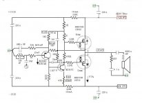
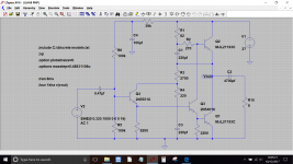
Thanks everyone. Just the right tonic for winter. Be a bit careful of my 4046 design ( nichoch, thanks , add 1K to the VAS load as it seems to be missing if it's not my screen ). I had a familly crisis at the time so not really finished. I was starting to like it. The 470R between FET's is ball park value for that batch. The 47R resistor to the BC547 emitter can be tuned ( 16R might be good, 47R softer, 0R more punch ). Be very sure DC offset is stable before risking speakers. I used 4 x 1000uF non polar for safety. The way I do the DC adjustment it is not my best design moment. All the same better has greater risks. One way to do that is use a long tail pair input and use the Naim trick. That is to use different resistors on the collectors that force the second harmonic distortion to be like a single input transistor. If you feed the signal into the feedback arm you might well win all your design goals. DC offset would be low.
John. Thanks for the data. Did we get near 2% THD open loop if every mod tried? Rod Elliott says put a 0R1 in TR1 emitter.
John. Thanks for the data. Did we get near 2% THD open loop if every mod tried? Rod Elliott says put a 0R1 in TR1 emitter.
I just bought JLH Class A amp 1969 version off ebay to use while I rebuild my 300B amp. It sounds good
and will substitute very well I think. Had a peep inside and was surprised to see that it uses pnp o/p transistors Mj15025.
Ive built JLH class A's in the past but never came across a pnp version. Ive had a look on google and have seen a pnp version
mentioned but no details. Does anyone have more detailed info like a schematic. suitable transistors and why a pnp version ?
There is no reason a PNP version should perform any differently to the original, particularly seeing as modern PNP output transistors are way better than they were 40 years ago. This is either from this thread some time back or a different one where the same thing got asked.
Remember that it now becomes positive earth. Substitute NPN for PNP and vice versa. Reverse polarity of all electrolytics and reverse the supply.
Remember that it now becomes positive earth. Substitute NPN for PNP and vice versa. Reverse polarity of all electrolytics and reverse the supply.
Attachments
There is no reason a PNP version should perform any differently to the original, particularly seeing as modern PNP output transistors are way better than they were 40 years ago. This is either from this thread some time back or a different one where the same thing got asked.
Remember that it now becomes positive earth. Substitute NPN for PNP and vice versa. Reverse polarity of all electrolytics and reverse the supply.
in my case, I had a large amount of pnp which I did not know what to do, it allowed me to use a few
The Goodmans Module 80 was all PNP class AB. My brother thought it was a germanium design updated from Thorn EMI to 2N2955. If you have one fit new caps and replace the VAS emitter diode with a resistor to give it the same DC points. If you do IM distortion drops nicely. The guy he did it for took it to shops when buying new items. He was never tempted to upgrade. Some dealers were honest enough to say it sounded very good. There was a version with Lenco GL75 turntable built in. That could be very nice. Most Germanium designs were all PNP.
- Home
- Amplifiers
- Solid State
- JLH 10 Watt class A amplifier