Try Cadj and Co = 10uF solid tantalum. Both close to the LM317.I don't really understand how to do the calculation for choosing right output capacitor according to the article, so the Rd in this case, could be the esr or extra resistor added.
Excerpt from TI datasheet attached.
Attachments
Because in a real circuit there is inductance, resistance and delay between the regulator and the load, deoupling is generally more effective closer to the load.
In the paper, a 220uF cap on the output of the regulator needs a 1 ohm resistor in series to ensure good stability. Whereas a smaller cap can work with a smaller resistor.
So a smaller cap can give lower HF impedance.
But, beware, this is a simplistic linear analysis. The big cap might work better if the transient load might take the regulator out of its linear operating area.
But what is your circuit more susceptible to? A bit of HF ringing or a slower recovery from a step load? The HF ringing at the regulator might be well damped by the time it reaches some other area of your circuit....
I don't design audio for a living, but in what I do design I've always found a fairly small capacitor on the output of the regulator plus local decoupling close to every op amp and mostimportantly every digital IC has worked well. If you want to be more advanced than that, I'd start looking at SPICE simulations of the whole power circuit, but be sure to include wiring inductance and PCB traces etc.
Also you need to know what loads the rails will face, having a really nice response to a 100mA current step might not help with some other load.
I have a copy of the T.I. LM4562 datasheet and there isn't any "page 59 to 82". MIne is a 39 page document. Please state exactly what your point is.Take a close look at Fig. 59 to 82 of the 4562 datasheet. Patrick

If you want to be more advanced than that, I'd start looking at SPICE simulations of the whole power circuit, but be sure to include wiring inductance and PCB traces etc.
Thank you for the good advice. I'll run some simulation. I thought the analysis is better than simulation. So I can say for the load to see power impedance, what it saw is the 2 decouple capacitor ESR ESL + trace inductance from cap to load?
My load is super light, 6mA + 1mA audio analog signal+ Vref current. and I put led to ensure it pulls enough current for regulator to work properly. Maybe I don't even need any cap besides decoupling 😀
Last edited:
If it doesn't have any load steps, or big AC loads, you mostly only need to worry about the input side..... Maybe I don't even need any cap besides decoupling 😀
But it's still a power rail not a voltage reference....
Maybe I don't even need any cap besides decoupling 😀
You don't. If you are worried about adding larger output caps or extra op-amp bypassing add a small series resistor. Besides decoupling it from the regulator rising impedance this also forms a RC filter. Place it near the op-amp's electrolytic also paralleled with a ceramic cap. (standard linear bypassing) Or you can model this death and still get it wrong.
Answer to post#22
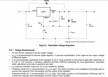
As described in page 4, in order to get C and Rd value:
First measure output impedance of your PSU across the selected frequency range (with test jig described in page 6), draw in on the impedance paper (attached). It should looks like the one in figure one: very low value in DC and low frequency then higher value asymptotic or still rising in high frequency).
Then draw your target max impedance on the paper, it’s a straight horizontal line on the paper. This is the goal you want to achieve. That mean that your goal can’t be ‘the best’, or ‘the lowest’, etc…it has to be value target value.
Then identify the break frequency (f0) of the RC network (also called Boucherot cell or Zobel network): it should be 0.4 * fx where fx is the frequency at which the output impedance curve cross the max impedance line.
Then, as f0=1/(2*Pi*Rd*C), and Rd = the max impedance (your goal), you have C with C=1/(2*Pi*R*f0).
As in real life cap have an ESR, the real resistor to use is R=Rd-ESR as R in in serial with the cap ESR.
But ESR is not always specified or well know, a trick may be use well known very low ESR cap (such as Panasonic F series: FR, FM, FC if you are in the µF range or any other film or ceramic ones on lower ranges). It allows to forget ESR and to have R=Rd. But this is only true if Rd not to small: let’s say > 0.2Ω otherwise ESR may get back significant across Rd.
Forgot to mention that the paper pdf is coming from : Printable Paper
I read the paper few times, indeed very interesting. But I find it hard to implemented numbers on the charts. What would be your practical suggestion for C1/Rd1, C2/Rd2 on LM317 application to lower high frequency impedance?
As described in page 4, in order to get C and Rd value:
First measure output impedance of your PSU across the selected frequency range (with test jig described in page 6), draw in on the impedance paper (attached). It should looks like the one in figure one: very low value in DC and low frequency then higher value asymptotic or still rising in high frequency).
Then draw your target max impedance on the paper, it’s a straight horizontal line on the paper. This is the goal you want to achieve. That mean that your goal can’t be ‘the best’, or ‘the lowest’, etc…it has to be value target value.
Then identify the break frequency (f0) of the RC network (also called Boucherot cell or Zobel network): it should be 0.4 * fx where fx is the frequency at which the output impedance curve cross the max impedance line.
Then, as f0=1/(2*Pi*Rd*C), and Rd = the max impedance (your goal), you have C with C=1/(2*Pi*R*f0).
As in real life cap have an ESR, the real resistor to use is R=Rd-ESR as R in in serial with the cap ESR.
But ESR is not always specified or well know, a trick may be use well known very low ESR cap (such as Panasonic F series: FR, FM, FC if you are in the µF range or any other film or ceramic ones on lower ranges). It allows to forget ESR and to have R=Rd. But this is only true if Rd not to small: let’s say > 0.2Ω otherwise ESR may get back significant across Rd.
Forgot to mention that the paper pdf is coming from : Printable Paper
Attachments
Last edited:
Ah, yes, my bad. Thanks for the link. My datasheet didn't have numbered figures.http://www.ti.com/lit/ds/snas326k/snas326k.pdf
I said Figure, not page. Ciao,Patrick
So, the positive supply PSRR is quite good: -110 db up to 10 KHz, then rising 6db/octave to a maximum of -80 db @ 200 KHz.
The NEGATIVE supply PSRR is NOT so good: -110 db up to ~200 Hz, then rising 6 db/octave to a maximum of -50 db @ 200 KHz.
So, the LM4562 is very good at rejecting ripple (120Hz), but not very good at rejecting high frequency noise from the negative supply. Even at an audible 20 KHz, it's only rejecting -70 db. BUT a 0.1 uF decoupling cap right at the IC power pin should reduce that 20 KHz noise another 20 db into inaudibility.
Isn't 0.1uF about 80ohms at 20kHz?Ah, yes, my bad. Thanks for the link. My datasheet didn't have numbered figures.
So, the positive supply PSRR is quite good: -110 db up to 10 KHz, then rising 6db/octave to a maximum of -80 db @ 200 KHz.
The NEGATIVE supply PSRR is NOT so good: -110 db up to ~200 Hz, then rising 6 db/octave to a maximum of -50 db @ 200 KHz.
So, the LM4562 is very good at rejecting ripple (120Hz), but not very good at rejecting high frequency noise from the negative supply. Even at an audible 20 KHz, it's only rejecting -70 db. BUT a 0.1 uF decoupling cap right at the IC power pin should reduce that 20 KHz noise another 20 db into inaudibility.
So you might want something a bit bigger as well.
Or you need the supply cleaner than 50dB up on the noise floor you will accept.
It may be worth checking whether the PSSR is reference to the input or the output.
It's worth having the 0.1uF for HF decoupling though, because MHz impulses on supply or signal lines can have effects at lower frequencies.
It's worth having the 0.1uF for HF decoupling though, because MHz impulses on supply or signal lines can have effects at lower frequencies.
Looking at it from the op-amp to the outsides. The devices data book results wouldn't be repeatable w/o good supply bypassing. The small value ceramic bypassing is all about the op-amps stability (the frequencies where the gain and phase margins are found >1MHz ) than any outside filtering or intermodulation. Also w/o good supply bypassing feedback on DC paths becomes an issue. Many analog designers also include small value electrolytic cap in parallel depending on PCB layout and other system level details. e.g. Op-amp's driving low impedances absolutely need extra help on stable DC, they pull lots harder on the supply rails.
Last edited:
I don't disagree with anything in the post above.
Good broadband supply decoupling should generally be assumed essential IMHO.
Good broadband supply decoupling should generally be assumed essential IMHO.
And here is the result of a signal impressed on the power supply rail -- instead of looking at PSRR (signal impressed on the supply to the regulator) look at how the regulator propagates problems.
First the LM317, second the LT1963A, third Per's SJOSTROM:
First the LM317, second the LT1963A, third Per's SJOSTROM:
Attachments
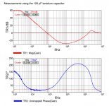
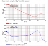
I guess I need to spell this out. The comparison you are making is not valid because one graph applies to a system with higher order than the other and so the phase difference is explained by this rather than capacitor type.Omicron Lab Application Note on Regulator Stability -- 100uF Tantalum vs 100uF Aluminum Electrolytic -- you can see that the phase margin is inadequate using the tantalum:
Check the application note in case you mixed something up.
Doesn't look too clever at 8MHz with the electrolytic either.Omicron Lab Application Note on Regulator Stability -- 100uF Tantalum vs 100uF Aluminum Electrolytic -- you can see that the phase margin is inadequate using the tantalum:
The LM317 is not intended to be loaded with big caps.
Big caps which don't look so capacitative at higher frequencies might be a slightly less bad idea.
Generally, why would anyone think it's going to be a good idea to make the load capacitance 100 times what the datasheet suggests?
I see 90 degrees of phase margin. What's the problem?Doesn't look too clever at 8MHz with the electrolytic either.
Why do you say that?The LM317 is not intended to be loaded with big caps.
TI claims the LM317 is unconditionally stable and it contains sophisticated self-protection circuits. So it can be used for a wide diversity of loads. Why not a big cap? In what sense is it a bad idea to use a large capacitor load?Generally, why would anyone think it's going to be a good idea to make the load capacitance 100 times what the datasheet suggests?
Hey trader, get this, remember my Maplin amp experiment?.......well, once upon a time I made a regulated supply for it using LM317/377, input was about 63V, output about 60V with 6800uF per rail, worked perfectly
- Home
- Amplifiers
- Power Supplies
- LM317 load capacitance