No, this is one of the reasons that is holding me back from sharing a PCB, I will definitely run it by him before I consider doing such a thing. I was mainly just thinking of making a personal PCB for my own system.
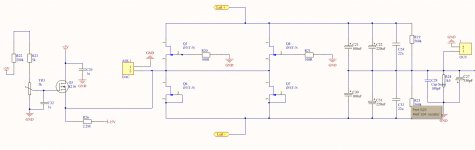
Jjazz, I had a look for the schematics and couldn't find it. Ill attach something similar to what im currently using. The only difference is its configured as SEN not CEN.
Ryan
Jjazz, I had a look for the schematics and couldn't find it. Ill attach something similar to what im currently using. The only difference is its configured as SEN not CEN.
Ryan
Attachments
Last edited:
Hi Ryan. How can I check if my pcb works? thank you very much.
Best regards
Hi Jjazz,
Which PCB are you referring to?
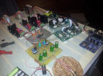
I bought the pcb and I welded the pieces (have to review any)
I believe that in order to know if everything works properly and does not spoil the dac chip tda1541A is necessary to weld some resistance and measure the voltage. I refer to this. What resistance and tensions which is necessary to measure?, if I am not mistaken is the way to check if everything is soldered correctly. I don't have much experience in this, I am rather an assembler.
I prefer to use the already welded pcb, so I'm on the interest list, but as there is no date I will run the risk of test which I have welded.
Thanks a lot
Hi Jjazz,
Yes it is recommended to check the voltages before you put in the 1541 chip. Use dummy loads to test the regs.
Use:
180R for +5 and - 5
510R for -15
If you dont have exact values dont worry, approximate values will be ok.
I'll update you on the populated PCB very soon.
Ryan
Yes it is recommended to check the voltages before you put in the 1541 chip. Use dummy loads to test the regs.
Use:
180R for +5 and - 5
510R for -15
If you dont have exact values dont worry, approximate values will be ok.
I'll update you on the populated PCB very soon.
Ryan
Hi.
I'll place the order and I'm not sure if I need multiplexed two's complement- I2S or Simultaneous. I'm going to use IanCanada i2stopcm. Which of these two options do I need and what is the difference?
Thank you very much.
I'll place the order and I'm not sure if I need multiplexed two's complement- I2S or Simultaneous. I'm going to use IanCanada i2stopcm. Which of these two options do I need and what is the difference?
Thank you very much.
Hi jjazz,
If your using Ians i2s to pcm pcb then select simultaneous. It sounds much better. It basically introduces much less noise into the chip that causes jitter.
If your using Ians i2s to pcm pcb then select simultaneous. It sounds much better. It basically introduces much less noise into the chip that causes jitter.
Last edited:
Hi Ryan
I’m sure it is on this thread somewhere. I’ve tried the search function and manually looking through pages. But run out of patience.
Can you please direct me to an example (part number?) of the connectors you have used for the signals. I have direct experience of them only when I’ve come across them inside a commercial product but I’ve not known what they are called or what size to look for.
Thanks
Hi Ryan
I’m sure it is on this thread somewhere. I’ve tried the search function and manually looking through pages. But run out of patience.
Can you please direct me to an example (part number?) of the connectors you have used for the signals. I have direct experience of them only when I’ve come across them inside a commercial product but I’ve not known what they are called or what size to look for.
Thanks
Hi Clayton,
I always solder wires directly to the pads.
The pitch is 2.5mm.
Sorry but I'm not sure what connector you could use for this. I've always assumed soldering the best and lowest impedance method - which may or may not be an accurate assumption.
Let us know what you find.
Ryan
Hi Clayton,
I always solder wires directly to the pads.
The pitch is 2.5mm.
Sorry but I'm not sure what connector you could use for this. I've always assumed soldering the best and lowest impedance method - which may or may not be an accurate assumption.
Let us know what you find.
Ryan
I’m confused. And maybe not being clear, because you already have connectors on the board for bck le/ws data etc. These are the things I’m referring to. There are not solder tabs there are mini little SMA I think they are called?
I need to know what the thing is to match to those connectors
Ah sorry, I though you meant the current output pads.
These are U.FL coax. U.FL-2LP-04N1-A-(70) Hirose Electric Co Ltd | Cable Assemblies | DigiKey
Cheaper ones:
2015357-3 TE Connectivity AMP Connectors | Cable Assemblies | DigiKey
These are U.FL coax. U.FL-2LP-04N1-A-(70) Hirose Electric Co Ltd | Cable Assemblies | DigiKey
Cheaper ones:
2015357-3 TE Connectivity AMP Connectors | Cable Assemblies | DigiKey
Last edited:
Ah sorry, I though you meant the current output pads.
These are U.FL coax. U.FL-2LP-04N1-A-(70) Hirose Electric Co Ltd | Cable Assemblies | DigiKey
Cheaper ones:
2015357-3 TE Connectivity AMP Connectors | Cable Assemblies | DigiKey
Thanks
Populated PCBs
I'm now accepting new orders for populated PCBs.
Distinction-1541 v2 Populated PCB
Ryan
I'm now accepting new orders for populated PCBs.
Distinction-1541 v2 Populated PCB
Ryan
Hi ryanj,
Can you please tell me the dimensions of the DAC PCB : ?length, breadth, hight
Thank you
Johnnny
Can you please tell me the dimensions of the DAC PCB : ?length, breadth, hight
Thank you
Johnnny
Hi ryanj,
Can you please tell me the dimensions of the DAC PCB : ?length, breadth, hight
Thank you
Johnnny
Hi Johnny,
PCB measures 97mm x 88mm x 20mm when fully populated.
Ryan
- Home
- Source & Line
- Digital Line Level
- TDA1541A Diy Pcb - "Distinction-1541 v2"