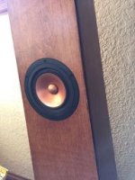
Tom,
No clue about LA software. I use MJK's MathCAD worksheets.
However...if it were me, I would raise the tuning freq & try removing the stuffing. Then line the back surface only w/ either felt or (what I use) Parts Express 0.5" sonic barrier foam. I've built half a dozen Mets, and that's what has worked for me. My first build more than a decade ago was a Fostex FE108eS, as designed by Scott L (IIRC). There was some confusion about the stuffing back in those early days. I lined ALL interior surfaces w/ 0.5" foam. Totally killed the sound. After ripping out the foam on the front & sides, it sounded quite good. I think in the larger builds I might have used a bit of Accoustastuf near the very top (very light stuffing), then switched to foam well above the driver.
Cheers, Jim
All good ideas. With my Fostex 127 Met it sounded better with half of the stuffing gone. I have some recycled cotton carpet padding I have been using for lining.
By tuning higher, do you mean shortening the vent tube?
I sent you a private message.
-Tom-
By tuning higher, do you mean shortening the vent tube?
I sent you a private message.
-Tom-
Tom,
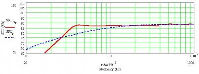
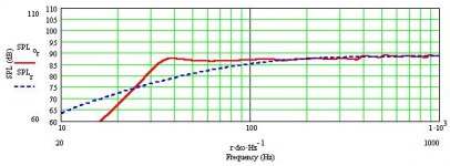
I ran models for the dimensions you put in your PM, then for the ones in your DIYaudio post.
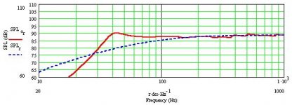
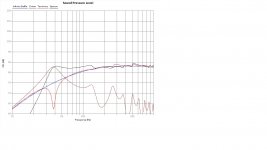
First two images are for L=54, Z(d)=24, S(0)=2x4, S(L)=7.5x9.5, D(p)=1.75, L(p)=1.5
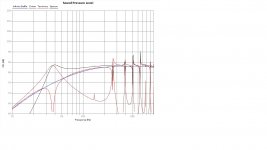
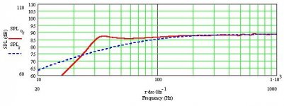
Images 3 &4 are for L=60.5, Z(d)=29, S(0)=2x4, S(L)=8x10, D(p)=1.75, L(p)=3
From the impedance plots, you can see that the smaller box is tuned to about 39 Hz, where the larger box is tuned to about 29 Hz. For my taste, the smaller box is the better choice. Don’t know if BSC would be needed. I have used BSC on most of my builds, but sometimes it doesn’t seem to be necessary.
If the port chuffs, then you will need to enlarge the diameter and increase the length. My preference would have been for at least 2” diameter, but if it works for you, then it’s all good.
If you don’t like the 2 dB rise before cut-off, you can play w/ the box dimensions to lower the box Q.
Cheers, Jim
Attachments
I agree with Jim, the bump before rolloff is not a good thing to have. Makes for what is perceived as "sluggish" bass.
In general I try to aim for as straight a response until roll off, even sometimes going for a slight downward slope.
It does not give the deepest extension, but a very clean bass response at the expense of a few Hz of extension.
In general I try to aim for as straight a response until roll off, even sometimes going for a slight downward slope.
It does not give the deepest extension, but a very clean bass response at the expense of a few Hz of extension.
Note that Jim's pictures are for smaller box first, larger box second, and mine are opposite.
Why a port diameter of 1.75"? I ordered port tubes of 4" x 2" but the actual ID was 1.75"!
I am happy that there is such good agreement between the Leonard Audio models and the Martin King models.
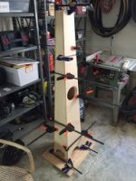
I am planning on building a pair of the second box. I learned a lot about building a Met with all those 3 degree angles so time spent building the first box was not wasted. If they turn out they will be at Burning Amp, November 12th.
Hajj,
Planet 10 has made the same point about the bass bump, "No second derivatives" is I think the way he put it.
In the models that bump can be eliminated or accentuated just by changing the amount of stuffing.
It might be useful to try stuffing the port tube to tame some of the TQWT peaks.
-Tom-
Planet 10 has made the same point about the bass bump, "No second derivatives" is I think the way he put it.
In the models that bump can be eliminated or accentuated just by changing the amount of stuffing.
It might be useful to try stuffing the port tube to tame some of the TQWT peaks.
-Tom-
Planet 10 has made the same point about the bass bump, "No second derivatives" is I think the way he put it.
There is always a 2nd derivative. The full statement: I prefer a roll-off curve where the 2nd derivative of the FR curve does not pass thru zero more than once.
This allows a bump at roll-off but only of a specific shape. In our miniOnkens the high-ratio high resistance slot vents supress this peak allowing for a “small” box where the bass has finesse.
dave
Something Interesting and Final Sanity Check
I continued to make some tweaks to the Leonard Audio model and ran across something interesting: Dropping the driver below the center of the line almost completely eliminates the first big peak. You can see this at the 160hz line in the picture. So is this a good idea or not?
Here are the inputs to the model. LL= 53", Top 2"x4", Bottom 7.5"x9.5", Driver @ 30.25", Vent 1.75"ID by 3", no stuffing (stuffing moderates the peaks).
5/8" Maple ply is in the basement, I'm ready to go!
Attachments
I continued to make some tweaks to the Leonard Audio model and ran across something interesting: Dropping the driver below the center of the line almost completely eliminates the first big peak. You can see this at the 160hz line in the picture. So is this a good idea or not?
Try placing the driver at 1/3 of the line length and 1/5 of the line length and check how this would affect the peaks in the response. (both of these should be from the top)
The current driver position is far from ideal from a practical point of view since it places the driver at a mere 23 inches from the floor
Tom,
Don’t move the driver further down from the top! Bad idea! Please begin by studying Martin King’s web site:
Quarter Wavelength Loudspeaker Design
I ran several sims for you. Images are as follows:
1&2: L=53; S(0)=2x4; S(L)=7.5x9.5; Z(d)=30.25; D(p)=1.75; L(p)=3
3&4: L=53; S(0)=2x4; S(L)=7.5x9.5; Z(d)=23; D(p)=1.75; L(p)=3
5&6: L=53; S(0)=2x4; S(L)=7x9; Z(d)=30.25; D(p)=1.75; L(p)=3
7&8: L=53; S(0)=2x4; S(L)=6x9; Z(d)=30.25; D(p)=1.75; L(p)=3
In the sims, I did not add series R, which would increase effective Q(ts) of the driver; if I were running the sims for myself, I would add 0.5R to account for speaker cables and connection resistance; exact value depends on your cables & connectors.
Look at how the bump before cut-off decreases with the reduction of V(b) in the last two cases. And I still might push the tuning up a bit higher as well; I might target 40 Hz region, then see how the bass looks relative to the lower mids. Again, no idea if BSC will be needed—depends on your room & speaker placement, among other things.
NOTE: I did not check to see if the driver will fit, i.e. clear the back panel; a supra baffle may be needed for the driver to fit; also check to see that the baffle or supra baffle is wide enough to hold the driver.
Please excuse any bluntness or errors, I'm just back from a bit of oral surgery & not in my 'happy place'.
Cheers, Jim
Attachments
Thanks Jim, lots to think about.
The MJK model confirms that the 30.35" driver placement kills the bump at 160hz, but perhaps at the price of a hole, and maybe larger higher-order peaks. I think I will explore moving the driver up at bit, accepting a bit of a 160hz bump. A half inch shorter vent will shift the tuning into the low 40's. I have an extra vent tube, so I will cut it progressively shorter until I discover what "too short" is.
The driver won't fit in the box at 23" with the current design. In any event the main panels have been cut, so my only options are moving the driver up to 25" or so, and varying the line length by an inch either way.
Hajj,
Your advice matches the usual recommendations for the Met. What I thought was interesting was watching the 160hz peak go away with the below centerline driver position. The room height of the driver will be 6" higher because of the base and down firing port.
Thanks for the help. I am disappearing down to the shop to fire up the router and mill some wood.
-Tom-
Metronome Tribute for Alpair 10.3M Completed
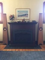
They got built! Speaker position got moved up to 28", still a bit below the center of the line. Also the vent is now 2"ID by 2.5" (a rolled up construction paper tube).
I am listening and the drivers are still on their break-in. Low bass is good, maybe mid-bass needs some help - we will see!
I am quite pleased with the finish, but there was some angst, as I had to sand down to bare wood and refinish both fronts and one back to cure blotchiness with the stain.
-Tom-
Attachments
Very cool, Tom. I've never had luck with stain, so glad you able to fix the blotches by sanding and restaining...they look great. I look forward to further listening impressions in time after breaking-in drivers.
Mario
Mario
Mario,
My significant other looked up a "This Old House" video on finishing, and they used wood conditioner prior to applying the stain. So I got some and used prior to the refinish and it worked a treat. Also I was using gel stain, which is apparently better with difficult to stain woods.
-Tom-
My significant other looked up a "This Old House" video on finishing, and they used wood conditioner prior to applying the stain. So I got some and used prior to the refinish and it worked a treat. Also I was using gel stain, which is apparently better with difficult to stain woods.
-Tom-
I've never had luck with stain
homemade wood conditioner - Google Search
When and When Not to Use a Pre-Stain Wood Conditioner
GM
Metronome Tributes at Burning Amp 2017
I got a bunch of really nice comments.
http://russbutton.com/Russ/audio/2017BurningAmp/IMG_20171112_123219.jpg
Since my last post, I took a skill saw and cut 4" off the top to firm up the mid-bass. The revised specs are 2.5"*4.5" top, 7"x9" bottom, 49" line length, driver at 24", and 3.5"x2"ID vent. I also took out almost most of the stuffing (they have carpet padding front and back for the top 30" and padding on either side of the driver.
They sound great!
-Tom-
Nice work Tom V, and good to know that you've got the sound sorted out. 🙂
What amp are you using now? What did you try out at BA 2017?
What amp are you using now? What did you try out at BA 2017?
What amp am I using now? A $50 SMSL SA-36.
At BA 2017 I used Paul's Not an Amp Camp Amp, and Nelson Pass's ACA 1.1.
Needless to say, building a good amp is priority 1 for the coming year.
At BA 2017 I used Paul's Not an Amp Camp Amp, and Nelson Pass's ACA 1.1.
Needless to say, building a good amp is priority 1 for the coming year.
Metronome Tributes - Final Design?
I have been playing with the design some more, knowing that I am getting close based on the performance of the Version 0 cabinets that I took to Burning Amp.
I also believe that the cabinet will work with different drivers, so I have modeled it with the Mark Audio Alpair 10.3M, the Pluvia Eleven, the Alpair 10.1P and a driver I have been interested in, the Tang Band W5-2143. The only difference is the vent length.
Top 3.5" x 1.5"
Bottom 9" x 7"
Line Length 49"
Driver at 24.5"
Vent 2" ID. 10.3M and Pluvia 11, 4.5". 10.1P 3.5", W5-2143 2.5"
Will all the experts take a look and tell me if I am on the right track?
Thanks! (Leonard Audio response charts in the following posts)
- Home
- Loudspeakers
- Full Range
- Metronome for Alpair 10.3m and 12p

