Hi Scott,
Ahhh, of course! But I still don't see the use for these signals.
-Chris
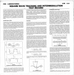
CBS test record has square wave, too.
Attachments
Triangular shaped grooves, involving progressively increasing angles from 5 thru 50 deg, are part of what is needed for a proper trackability test.
As Scott says, in the absence of RIAA playback, these nominally would be programme material square waves of progressively increasing amplitude. Well almost, they'd have flat tops and bottoms.....but the rise time/slew rate would be set by the curvature at the top/bottom of the triangular grooveshape. Arranging for it to not exceed 500G acceleration should make that test trackable.
This curvature/acceleration is another key trackability test. One could keep the triangular-wave groove angle constant at say 20 deg, and vary the curvature/acceleration at top/bottom in steps of 100G or so from 100G to 2000G........
To synthesise these files, one would simply need to generate square wave programme material of variable amplitude (angle) and slew rate (curvature). Probably at a repetition rate slow enough to allow a decent time to inspect cartridge output waveshape.
Lastly, one could test for 'jolt' by creating a 2nd order slew rate curve for the synthesised square wave. The limit at which acceleration change is tolerated.
These, IMO, are some of the proper crux of trackability tests that haven't been done before AFAIK, and would be revealing about performance aspects of cartridges/setups and rigs that really matter to playback.
LD
Last edited:
Triangular shaped grooves, involving progressively increasing angles from 5 thru 50 deg, are part of what is needed for a proper trackability test.
This brings up the point that some tracks might inevitably want no RIAA pre-emphasis and conversely the user would need both an RIAA and flat preamp though RIAA could be done in software/DSP.
Is there much of a noise penalty doing SW inverse RIAA for those who don't want to have more pre-amps around? (not me, more is good 🙂).
Is there much of a noise penalty doing SW inverse RIAA
Even if that could be debated for the purposes of a test record it should not matter. Even the miniDSP does a credible job.
Updated track list
SIDE A
Track order not definitive
SIDE A
- 3150Hz Speed, wow+flutter
- 1kHz Reference level 5cm/sec, distortion, phase
- Left identification
- Right identification
- Signal in phase
- Signal out of phase
- Pink Noise (level?)
- White noise (level?)
- L+R
- L-R
- Rotating phase
- Crosstalk test
- Silent Groove for Rumble (maybe locked)
- Low frequency sweep for cart & arm resonance
- 440 Hz sine 0dB
- Square wave 1
- Square wave 2
- Full range sweep @5cm/sec
- Silent groove
- Full range sweep 24dB below reference
- same 18dB below reference
- same 12dB below reference
- same 6dB below reference
- same @ reference
- same 6dB above reference
- same 12dB above reference
- same 18db above reference
- VTA test
- Trackability test
Track order not definitive
I was thinking 9&10 fixed frequency. Maybe 1K. An electrical phase check and perhaps cart alignment.
Track 5&6 should be an auditory test, so maybe low passed noise. Just to allow a quick check by ear if polarity is correct. Could even do Low-Mid-High to check different parts of the system (speakers, mostly).
Track 5&6 should be an auditory test, so maybe low passed noise. Just to allow a quick check by ear if polarity is correct. Could even do Low-Mid-High to check different parts of the system (speakers, mostly).
For phase test I was thinking something like the attached files.
Low, Mid, High in phase, 4 secs each
Low, Mid, High, out of phase, 4 secs each
It's a handy test that allows you to hear if there are any polarity problems. More a quick "by ear" polarity test than anything else. Don't know how well this could be cut into vinyl.
Low, Mid, High in phase, 4 secs each
Low, Mid, High, out of phase, 4 secs each
It's a handy test that allows you to hear if there are any polarity problems. More a quick "by ear" polarity test than anything else. Don't know how well this could be cut into vinyl.
Attachments
Try using a 20 KHz constant tone for maybe 30 sec. From that you can infer both level and azimuth. You could precede that tone with a 1 KHz tone at the same level. I have no idea what a suitable level might be.
A 20 KHz tone for azimuth would be very telling, and it is low enough in frequency that almost every system should be able to reproduce it. If the cartridge is so cheap that it can't reproduce a 20 KHz tone, don't worry about azimuth too much. Such a cartridge will be destroying the test record anyway.
-Chris
How about 10Khz Chris? From reading threads written by guys who actually master and cut records, they top out at 15K. Although we hope to push our sweeps higher, 10K ought to be fine enough for cart alignment, don't you think?
Should be. I'd still stick a 20 KHz track on it though, maybe as a slightly shorter track. There are LPs that have this HF information on them, so I wouldn't go so far as to say that a 20 KHz track wouldn't be seen in the wild.
-Chris
-Chris
10-4 
We'll have to find out how hot a 10K or 20K signal can be cut. Remember, the reverse RIAA applied to the cutting master has 20dB of boost at the top end.
We'll have to find out how hot a 10K or 20K signal can be cut. Remember, the reverse RIAA applied to the cutting master has 20dB of boost at the top end.
This thread started as an offshoot from the Turntable Speed Stability thread, but the proposed tests so far seem to be steady state signals, many of which can be found on discs that are currently available. The ‘TSS’ thread Turntable speed stabilty found that unwanted headshell motion can cause significant FM/pitch variation due to stylus scrubbing. These effects are influenced by tonearm geometry and tonearm damping, so that the measured stability of the signal output from the cartridge can be affected as much by tonearm characteristics as by the turntable drive characteristics.
I propose a dynamic test signal that I’ve not seen on any test discs. Groove modulation increases stylus drag. We know that stylus drag force applied to a tonearm with an offset angle causes skating. Skating force, and the stylus deflection it causes, is not constant. It varies, and it can vary dynamically, depending on groove modulation level, or amplitude. If the groove modulation/amplitude varies at a rate near the mass/compliance resonance frequency, the varying stylus drag could stimulate headshell motion at the mass/compliance resonance frequency. The attendant stylus scrubbing would cause dynamic FM/pitch variation of the signal which would look like turntable speed instability, but the effect would be attributed to the tonearm characteristics and not necessarily associated with the turntable drive. The band would be a carrier of suitable frequency, perhaps 1000 or 3000 Hz, and swept from 1 to 20 Hz or so. Odd as it may seem, such a signal could stimulate mass/compliance resonance even though it does not contain any low frequencies itself. The next band would be the same carrier signal, but unmodulated, which should theoretically yield a steady state condition without the influence of measured instability due to dynamic tonearm effects. In a perfect world, the measured instability observed from the two test bands would be the same. Comparing the diferences of the results from these two bands could help ferret out the relative contributions of tonearm dynamic behavior vs. turntable drive instability??
Ray K
Last edited:
Hi Ray,
That is what the 3150 Hz tone accomplishes. You'll notice this track is at both ends of the track so you can measure at the start and the end of the LP.
Dynamic signals are maybe useful to home users, but we need steady state signals to measure. There are "test discs" that have the dynamic signals. I don't own any as they are quite useless on a service bench. I happen to have a "Dynamic Signal Analyser", an HP 35665A, so maybe some dynamic signals might be sort of useful. It generally outputs dynamic excitation signals so it knows what to expect coming in.
I don't know about a white or pink noise track. Some instruments can use that, like my Audio Control RTA.
Best, Chris
Hi Ray,
I don't think we are talking about different things.
The amount of force that the stylus load asserts is really small and a good table should be able to continue running at the same speed. Certainly anything like a Thorens or Linn could be expected to ignore the added drag. Now, if you have a low friction platter mat, that might be a problem. Any sticky mat would completely bond the LP to the platter, eliminating the effects of minor drag changes. I guess if the tone arm bearings were loose, the arm might shift with changing load.
As you had suggested, a constant tone would be the easiest way to detect a speed change whether it was classified as FM (flutter), or a slow speed change (wow). Wow and flutter meters are designed to lock onto the 3150 Hz tone and show deviations from that. Something like a flutter meter (I retained one) would show shorter term changes which would be noticed by we humans. We wouldn't notice a small, slow change. For that you need a wow and flutter meter, or a way to compare the tone from the turntable and a stable frequency generator. Locked to the GPS network really makes that the last word in frequency comparisons.
Okay, so what are you getting at if it wasn't explained in this post?
-Best, Chris
I thought in the Stability thread that we established that stylus drag does not affect speed. But arm and headshell movement certainly does look like speed variation on the polar plots.
A special signal to detect this is a great idea. Although maybe I don't understand your swept carrier, anything new or unique like this is a certainly worth a try.
A special signal to detect this is a great idea. Although maybe I don't understand your swept carrier, anything new or unique like this is a certainly worth a try.
- Home
- Source & Line
- Analogue Source
- Test LP group buy