I checked photo shows R20 red:red:yellow 5% carbon = 220k
R1 & R2 = red:red😱range or 22k
Would leaving negative input floating cause problem?
R1 & R2 = red:red😱range or 22k
Would leaving negative input floating cause problem?
....
Would leaving negative input floating cause problem?
you had speaker connected , while neg leg was floating
you heard pretty much nothing
so , no harm
😀
however .... just chill out
when I was a youngster (somewhere in time of Dodo) , i was so exalted , while concocting my first PP tube amp ...... finally , spent two days searching why I had no sound in speakers ;
every point passed DC measurements , had no scope , had no gene (except finger)
chased more than one tail ...... finally found systematic flaw on both monoblocks - forgot to mount half inch wires connecting (meticulously mounted) signal caps in-between phase splitter and output toobz grids
wasn't last time Mighty ZM showing all his Mightiness .......

........ wanna hear what's happening when systematically swapping routes of pin 1 and pin 2 on XLR connections in preamp ?
everything works flawlessly , upon connecting drek to source and power amp , then .......

when I was a youngster (somewhere in time of Dodo) , i was so exalted , while concocting my first PP tube amp ...... finally , spent two days searching why I had no sound in speakers ;
every point passed DC measurements , had no scope , had no gene (except finger)
chased more than one tail ...... finally found systematic flaw on both monoblocks - forgot to mount half inch wires connecting (meticulously mounted) signal caps in-between phase splitter and output toobz grids
wasn't last time Mighty ZM showing all his Mightiness .......
........ wanna hear what's happening when systematically swapping routes of pin 1 and pin 2 on XLR connections in preamp ?
everything works flawlessly , upon connecting drek to source and power amp , then .......
it's either that ... or you forgot to flip power switch
beware ...... having "Audio" both in avatar and sig , presumes certain level of experience and knowledge
world is going younger and younger ... not that's a bad thing
🙂
beware ...... having "Audio" both in avatar and sig , presumes certain level of experience and knowledge
world is going younger and younger ... not that's a bad thing
🙂
I was hoping that the R3 to ground would have handled that. But Megohms is same as floating input.
I was hoping that the R3 to ground would have handled that. But Megohms is same as floating input.
What is total effective resistance of 22k in parallel with 1 Meg?
-ve In cannot be left floating, or you will have no gain.
Connecting -ve input to ground causes a huge ground loop on one channel (30mV) but other channel is fine. It plays loudly now. I even tried using a 10R resistor to ground and that did not help. Will need to debug. Any ideas?
I think I know what might be causing this. I am using a 3.5mm jack to flying leads with shared ground as quick and dirty test of sound. I will make up independent cables and try again.
I have a 400va 18vac toroidal trafo feeding parallel connected CRC PSU's at the AC input to the diode bridges. The CRC PSU is the one from here:
CRC Power Supply (Class A amplifier)
The ground after the second capacitor bank is connected to the clean side of a GLB (8R, 2 diodes, 100nF). The dirty side of GLB is connected to chassis and earth ground.
Each PSU has +/-24v and GND (to the common clean GND pin) to the amp modules.
I am away from computer so can't draw schematic yet.
considering that you have common secondaries for both PSU pcbs , you must establish common GND for both channels
that means - fat wire connecting main GND points of two pcbs , then main GND preferably being on exact middle of that fat wire
then , depending how you made overal grounding routes , maybe you'll need fat wire connecting main GND points of two channel pcbs
maybe shortest way of curing it is - that fat wire between two channel pcbs , without first mentioned
for least problems - either go with proper dual mono ( separate xformers or at least separate secondaries for each channel PSU) or usual common PSU for both channels
you have worst possible combo - common xformer to separate rectifiers and cap banks
I think I will order a pair of 18VAC trafo's and start over. Connecting a 12ga solid copper ground bus between the PSU's and tying the amps at midpoint actually made the problem worse! So, I am at a loss. When using SMPS, I don't seem to have the cursed ground loop chasing my tail problem. So, the amp is off the bench and will have to wait for a day when I have the dual trafo's or maybe switch to SMPS.
there are several places where you can try to establish common path between two grounds , and which one (or even two ) will work best is thing to try
-only between two channel pcbs main GND points
-between two output GND points of PSU pcbs
-between GNDs where they first established (sort of) at first C in CRC
anyway - as I wrote previously - worst solution is when you have half of two approaches ( dual mono vs. not so dual ) ....... almost situation as being little pregnant 🙂
you can also try to include series resistor of 10-22R in one channel's input GND
then to try NTC from GND to case , or directly GND to case
-only between two channel pcbs main GND points
-between two output GND points of PSU pcbs
-between GNDs where they first established (sort of) at first C in CRC
anyway - as I wrote previously - worst solution is when you have half of two approaches ( dual mono vs. not so dual
) ....... almost situation as being little pregnant 🙂you can also try to include series resistor of 10-22R in one channel's input GND
then to try NTC from GND to case , or directly GND to case
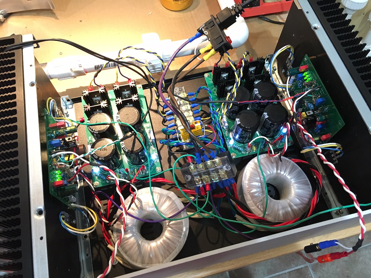
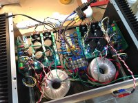
My dual Antek AS1218 toroidal trafo's arrived yesterday. Finally had a chance to install them into a dual PSU monoblock setup with the CRC's. The only common ground point between the two amps is now a ground from the second C in the CRC (where the amp power cables are connected) to a single "clean" ground point on the ground loop breaker (GLB). The other side of the GLB (a 8R resistor with two 10A10 diodes and a 100nF 250v film cap all in parallel), connects to chassis ground and earth ground. Running at 1.20amp bias and dc offset is about 10mV, still stabilizing. The output noise with inputs shorted is now 0.9mVac (not 0.1mVac as before), but this figure does not change when I plug the input into a DAC. Music is playing now and first few tracks on my XKi speaker fitted with a Tang Band W5-2143 sounds really good. Nice bass, articulate and clear while deep. Mids and highs sound very clear and fluid. Will listen more now. Here is a photo of the temp setup before I drill holes and hard mount stuff. It all fits nicely.
Thanks ZenMod, for the nice Babelfishing effort, the amp sounds really good.

Thanks ZenMod, for the nice Babelfishing effort, the amp sounds really good.
Attachments
Last edited:
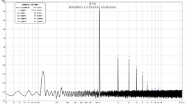
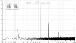
I just put the Babelfish J amp up to my measurement rig (8ohm 25w resistor and Focusrite 2i4) and am getting a rather high 0.21% THD at 2.83vrms into 8ohms. Is this normal - and predicted by simulation, or perhaps I have something off in my amp? One thing that is nice to see is that my linear PSU appears to be working very well now with no more "forest of noise" like I had before when running the single trafo on the M2. Here is the FFT for left and right channels driving 2.83v rms into 8ohm resistive load. Voltage on load read-out with 2k/22k voltage divider.
Left Ch:

Rt Ch:

Left Ch:
Rt Ch:
Attachments
What mosfets are you using?
What Bias?
How many mosfet pairs?
What source resistance on mosfets?
What Bias?
How many mosfet pairs?
What source resistance on mosfets?
- Home
- Amplifiers
- Pass Labs
- About possible Babelfish J interest