Something like this ?
.
Yes. I am not sure though that 50/3 is an optimal ratio.
One more trick: put a row of transistors with equal resistors in emitter close to each other, and wrap them all in a copper foil. One of them in the middle use as a sensor. The best current mirror I ever used. 🙂
> I am not sure though that 50/3 is an optimal ratio.
I want to have 150mA at the output stage (for headphones, not speakers).
So that is the ratio with 4mA opamp idle current.
Part of the 4mA is the base current of the output transistors.
Of course one can scale the 150:3 (or 50:1) up and down in resistor values.
I did not try to find the optimum, just to demonstrate working principle.
Patrick
Last edited:
What is output current limit of your opamp?
I would limit the ratio according to this current, to avoid frying of output transistors if output is shorted.
I would limit the ratio according to this current, to avoid frying of output transistors if output is shorted.
Opamp short circuit current ~ 25mA.
Output transistors are rated at 20W (so 1.3A at 15V).
50:1 still works.
Patrick
Output transistors are rated at 20W (so 1.3A at 15V).
50:1 still works.
Patrick
That reminds me of the first amp I ever built from a kit. AD149 outputs and 2N3702/4 for the others. Also remember it having 1 ohm emitter resistors.
I still remember the excitement of finally getting it to work, first on one channel and then the other. There were some mishaps on the way and a lot of learning in a short space of time. It sounded fantastic too.
I still remember the excitement of finally getting it to work, first on one channel and then the other. There were some mishaps on the way and a lot of learning in a short space of time. It sounded fantastic too.
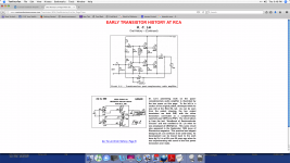
For historical reference, here is one of the first examples of effective solid state design. You might call it the Great-great grandfather of solid state amps. Kudos to Dr. Lin. I will follow his work further, (for myself). He was a true pioneer.
It is similar to the first power amp that I built when was a kid in 5'Th grade. I copied the schematic from Soviet record player Accord. I organized a rock group in my school then, and we needed an amplifier. 🙂
The main problem was, to find a NPN transistor!
Ampex used this sort of Lin design (in silicon) as late as 1968, but Lin appears to have been first, 1952, I think.
NPN Germaniums were quite rare in the mid 1950's. You probably had to work as a semi company to have access. Notice the output was quasi complimentary since high power Germaniums may not have existed then.
There are some really premium amplifiers using quasi-complimentary circuits today. They have pretty symmetrical behavior on the outputs which is not guaranteed on complimentary transistors (unless the NPN is degraded).
There are some really premium amplifiers using quasi-complimentary circuits today. They have pretty symmetrical behavior on the outputs which is not guaranteed on complimentary transistors (unless the NPN is degraded).
Dr. Lin mentions this in his oral commentary. However, there is a part # on the 1956 schematic. In 1952, however, he had to be an 'insider' to get such a part, I suspect.
I don't have any real problem with complementary bipolar devices, especially if they are voltage driven. However, power mosfets are a real problem and the N channel probably should be degenerated somewhat to more closely match the P channel complement. This is not much of a problem with Toshiba complementary jfets and their replacements, because they change the die area to match the Gm almost perfectly. Of course, then you have Cin differences, but in complementary differential service the C non-linearities tend to partially cancel between the N and the P devices.
I don't have any real problem with complementary bipolar devices, especially if they are voltage driven. However, power mosfets are a real problem and the N channel probably should be degenerated somewhat to more closely match the P channel complement. This is not much of a problem with Toshiba complementary jfets and their replacements, because they change the die area to match the Gm almost perfectly. Of course, then you have Cin differences, but in complementary differential service the C non-linearities tend to partially cancel between the N and the P devices.
NPN Germaniums were quite rare in the mid 1950's. You probably had to work as a semi company to have access. Notice the output was quasi complimentary since high power Germaniums may not have existed then.
There are some really premium amplifiers using quasi-complimentary circuits today. They have pretty symmetrical behavior on the outputs which is not guaranteed on complimentary transistors (unless the NPN is degraded).
The output is a 2N158 17 Watts! 2A/60V. I can't find mine. Copper case with a 1/4-20 tap in the top, only a bit bigger than a TO-5 mostly taller.
Demian you are showing your youth! But surely you remember the 2N170 NPN germanium RF transistor?
I remember the CK722 and the 2N107.... found them and a bunch of other oldies last year... threw them all out along with a bunch of rare new tubes, nuvistors, tunnel diodes and the like. If I did not use them back then, why hold on to them? Should have gone to a museum.
-RM
-RM
Last edited:
I remember the CK722 and the 2N107.... found them and a bunch of other oldies last year... threw them all out along with a bunch of rare new tubes, nuvistors, tunnel diodes and the like. If I did not use them back then, why hold on to them? Should have gone to a museum.
-RM
Next time eBay. There are folks who really want those things. The 2n107 is popular for guitar fuzz boxes. Nuvistors actually are still a good choice for radio receivers that have to work in strong RF fields.
Tunnel diodes have their best current use not exactly legal.
If you had enough junk you might have been able to pay for a semester!
On eBay junk sells, good stuff not so much. I pick up about $10,000 a year on stuff that used to go into the dumpster.
I donated a bunch of tube gear twenty years ago, surprisingly, it is now worth more than the equipment that has replaced it...
About 10 years ago I bought on ePay a box of stuff from Radio Shack. There was unopened GE-1 transistor there, I sold it back on ePay. It paid for the whole box including shipment.
So it was Lin who created the fashion of using voltage biased output emitter followers!
As guilty as charged!
As guilty as charged!
Just announced Harman is closing everything but the former AMX facility in Richardson Texas and the JBL site in Northridge CA. 650 folks loose their jobs.
- Status
- Not open for further replies.
- Home
- Member Areas
- The Lounge
- John Curl's Blowtorch preamplifier part II