I might switch out the bridge rectifiers and install some hexfred ultra soft recovery diodes.
If these show an improvement I'll post results.
Some diodes cost is high...
Do you try individual snubber first to improve your psu prrformance
with diy cheapo version or quasimodo v4 jig?
Simple, no-math transformer snubber using Quasimodo test-jig

I have 50 unused hexfred diodes.
I've been meaning to try them.
I will also try the snubber but I will try the diodes first on one channel.
I've been meaning to try them.
I will also try the snubber but I will try the diodes first on one channel.
On second thoughts it's pretty bloody easy to install a snubber on the power supply.
What value do you guys recommend?
Maybe I'll do that first.
What value do you guys recommend?
Maybe I'll do that first.
Cool PicoI have 50 unused hexfred diodes.
I've been meaning to try them.
I will also try the snubber but I will try the diodes first on one channel.
Article from Linear Audio magazine show tests
and 3 $ full bridge with his proper snubber can bring superior performance
if compare to 25 $ bridge de luxe without.
Soft recovery diodes type with snubber is to radar
 with jig on the scope. Numero Uno Top 1
Psu electrolitics bypassed with small polypro MKP or MKC's is another thing too try 🙂
On second thoughts it's pretty bloody easy to install a snubber on the power supply.
What value do you guys recommend?
Maybe I'll do that first.
Is bit more complicated not " universal " caps and resistors values
but if you do you own Quasimodo jig and with little practice
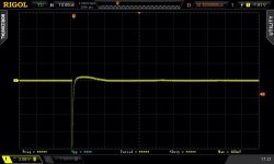
you made stop ringing your psu toroid after 5 minutes of work.
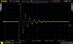
CheapoModo: quick and dirty transformer snubber bellringer jig
Smooth operator
Simple, no-math transformer snubber using Quasimodo test-jig
Happy snubbing 😉
Attachments

Even though the work that Mark did was truly excellent, I'm too lazy to go down that path.
I just want to see whether any simple changes bring about any improvements.
I'm interested to see whether the Hexfreds do bring improvements on a working class A amplifier, not just test jig.
I just want to see whether any simple changes bring about any improvements.
I'm interested to see whether the Hexfreds do bring improvements on a working class A amplifier, not just test jig.
I'm too lazy to go down that path.
I just want to see whether any simple changes bring about any improvements.
I'm interested to see whether the Hexfreds do....

Ok hope Hexfreds bring some improvements.
With non ringing toroidal they give you much more.
Silent background is one favorite music friend
If you have a square wave generator you can go QuasiModoExtraLight and see what simple changes bring about.I'm too lazy to go down that path.
I just want to see whether any simple changes bring about any improvements.
.

I'm interested to see whether the Hexfreds do bring improvements
Music flows better in the air ?
What your conclusion about Hexfred ultra soft recovery ?
Music flows better in the air ?
What your conclusion about Hexfred ultra soft recovery ?
Haven't had a chance to install them yet.
I'll try and get it done this weekend.
Haven't had a chance to install them yet.
I'll try and get it done this weekend.
Ok Pico i stay in tune 🙂
I'm getting ready to populate my boards. Is this the best guide at present?
to refresh your memory :
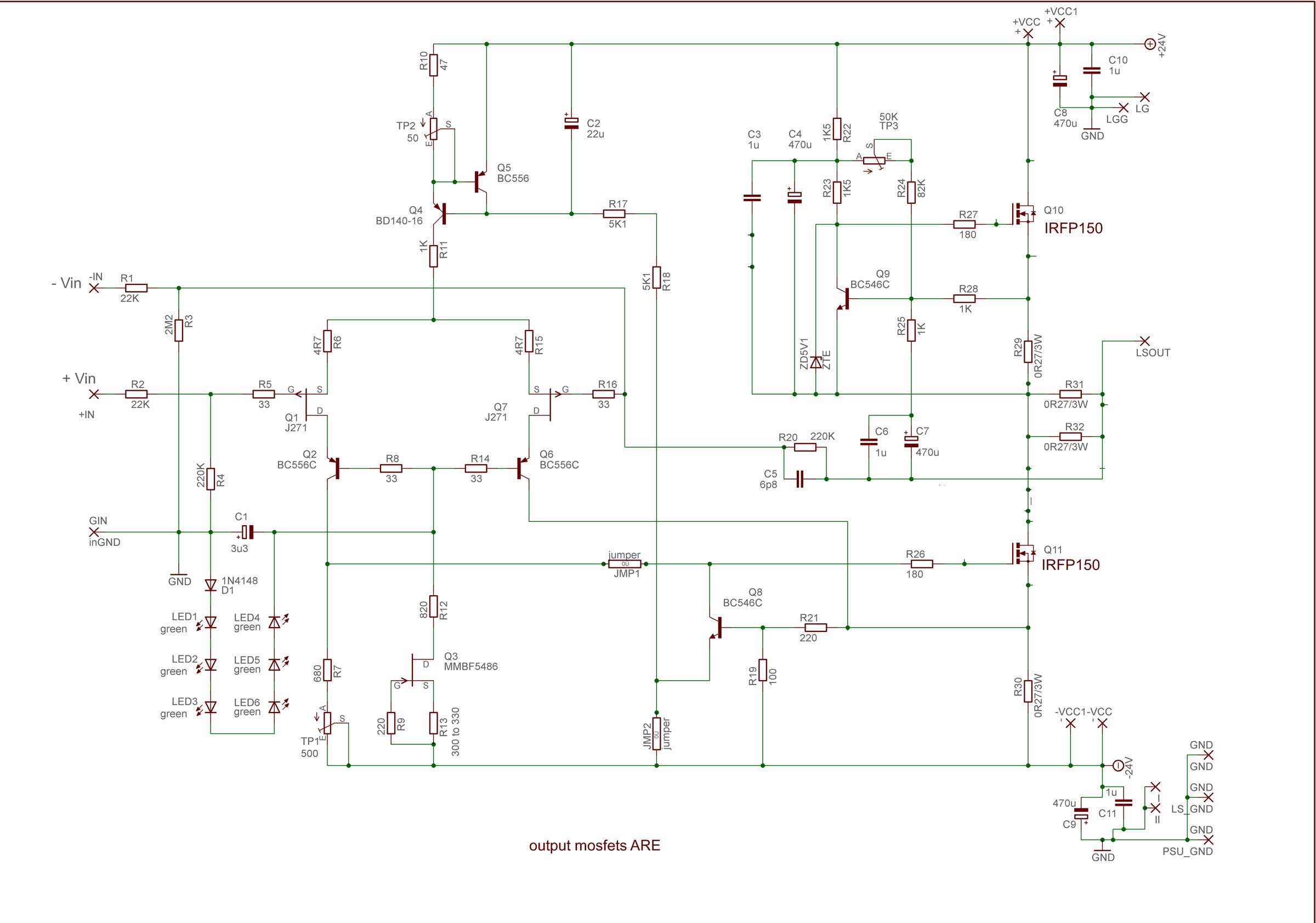
TP2 - set 10V across R11
then - with shorted inputs and no load on output .... TP3 is for Iq setting (desired Iq is measured as voltage drop across (any) mosfet source resistor), while TP1 is for output offset setting
ya know the drill - everything in temp equilibrium ..... put lid on , wait temperature to be stabilised , pull lid off - set in half** increments what you must set - put lid on , wait again
** half step to desired value
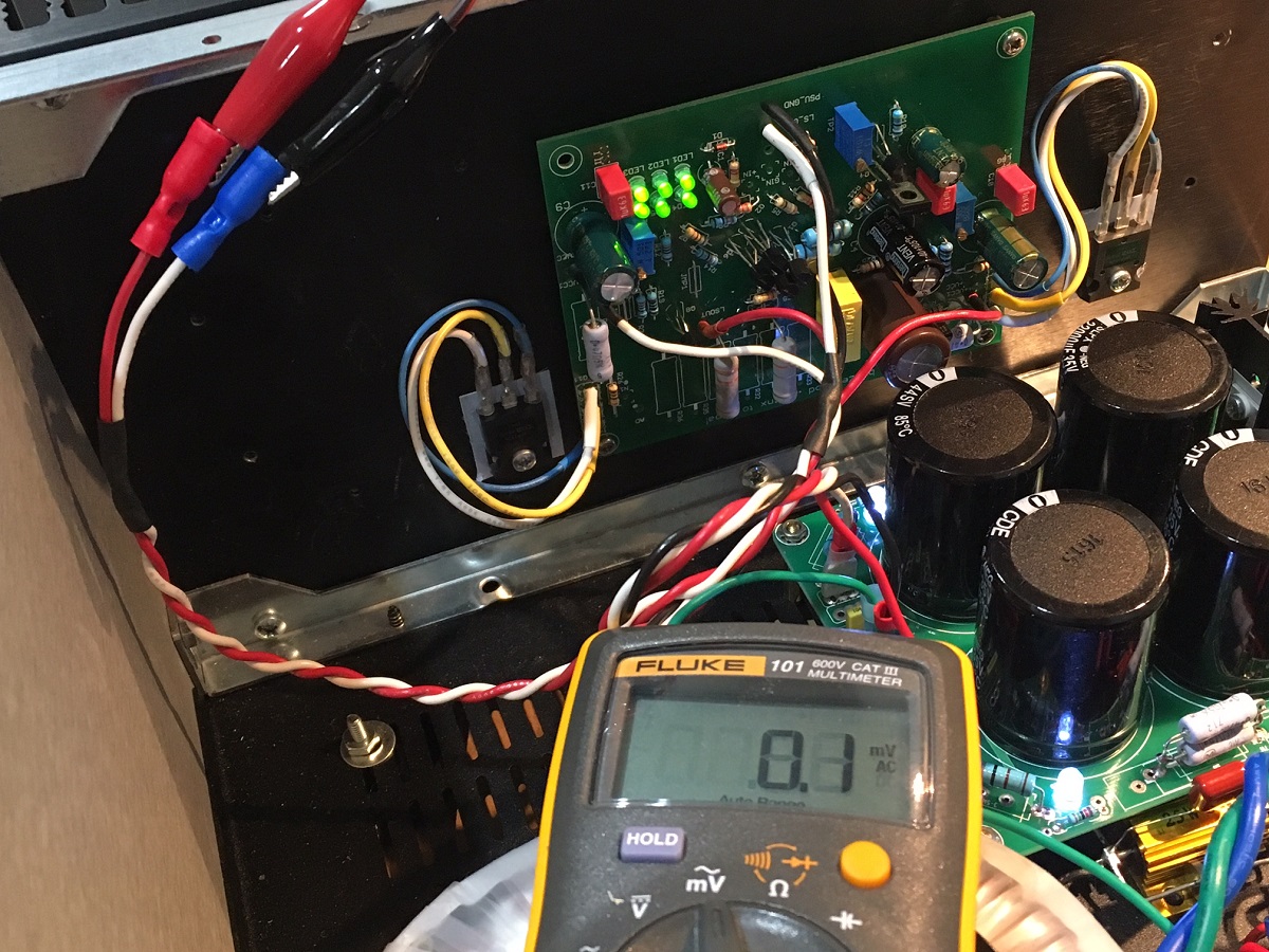
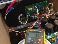
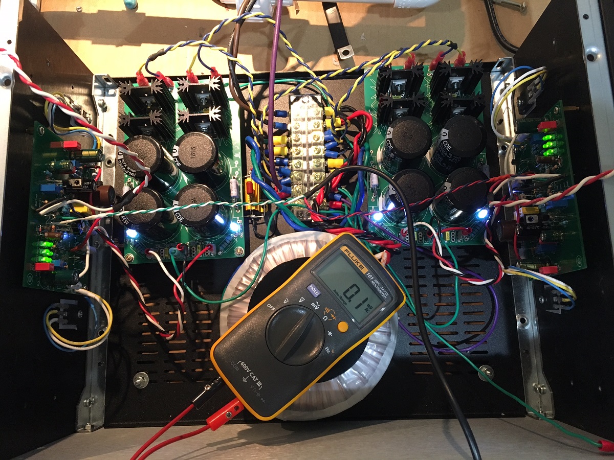
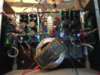
I fired up Ch1, luckily no magic smoke. 🙂 Set v across R11 at 10.0v (took quite a bit of turns). Set bias at 1.20 amps, output offset is still varying slightly as it warms up but no problem getting 0mV offset.
Output noise looks very promising at 0.1mV rms on Fluke 101. Could be used for a headphone amp at these low levels. Looks like I did my grounding topology correct too and no measurable hum.
Ripple on PSU rail under load is 26mV.
So far, an excellent start. Need to put flying leads on the other channel now for the IRFP150's.
So far, very promising...
Attachments
Both channels are working properly from bias, DC offset, and noise. However, there is no gain in the amp. 1.00vrms in = 1.00vrms out at speaker terminals. I am only driving +ve and GND of the balanced input. Do I need to do something special? All I can think of is that I set a feedback resistor somewhere off by factor of 10? So music is very weak when played on speakers.
Current is flowing through the MOSFETs as the amp is warming up. Still steady at 1.2amps. So not sure why I don't have music that has gain.
Is closed loop gain set by R20/R4 or R20/R2?
Current is flowing through the MOSFETs as the amp is warming up. Still steady at 1.2amps. So not sure why I don't have music that has gain.
Is closed loop gain set by R20/R4 or R20/R2?
Attachments
Last edited:
Yes, J1 and J2? ALso I connected a thick 12ga solid core copper wire from AD to AS on back side. I'm going to have to call it a night and resume tomorrow.
Is closed loop gain set by R20/R4 or R20/R2?
R20/R1, but only if there is something connected to -IN.
Ha, pico beat me
Last edited:
- Home
- Amplifiers
- Pass Labs
- About possible Babelfish J interest