Hello @MASantos
Standard (THT) PASS M2 printed circuit board.
110x120x2mm; 70µm; HAL; top silk; green --> 15 pairs batch = 12€ without postage
(blue, white, black = 14€)
MASantos - one pair
JP
Standard (THT) PASS M2 printed circuit board.
110x120x2mm; 70µm; HAL; top silk; green --> 15 pairs batch = 12€ without postage
(blue, white, black = 14€)
MASantos - one pair
JP
JPS64, will you be ordering extra amp boards? I might be interested in a pair if you do.
If you do, kindly, do a group buy, a pair for me too...PLEASE?
Thanks
EDIT...did not see post to Santos above!
(Shipping to UK?)
Last edited:
Before starting GB PCB M2 amplifier, here last documents.
JP
JP
Attachments
-
PAS_M2-CASCODE_SCH.pdf23.5 KB · Views: 253
-
PAS_M2-CASCODE_PBA-TOP.pdf34.1 KB · Views: 184
-
PAS_M2-CASCODE_PCB.pdf436.5 KB · Views: 150
-
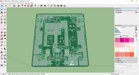 M2-PCB-TOP.jpg459.1 KB · Views: 870
 -
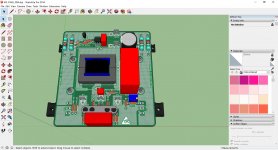
 M2-PBA-TOP.jpg378.3 KB · Views: 845
 -
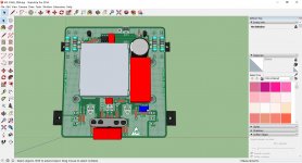
 M2-PBA-BOT.jpg384.6 KB · Views: 821
 -
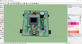
 M2-PBA-TOP_without_Shield.jpg379.9 KB · Views: 809
 -
 M2-PBA-TOP_AL_coupling.jpg361.8 KB · Views: 795
@MASantos - 1 pair
@wrath - 1 pair
@ brianco - 1 pair
@ KweeSong Lim - 1 pair
@Cambe - 1 pair
@mk57 - 1 pair
Checking tomorrow postage costs before starting GB PASS M2 thread.
JP
@wrath - 1 pair
@ brianco - 1 pair
@ KweeSong Lim - 1 pair
@Cambe - 1 pair
@mk57 - 1 pair
Checking tomorrow postage costs before starting GB PASS M2 thread.
JP
I've just fired up my M2. R13 and R14 are at .638 so it seems to be biasing up just fine. However I have 2.8 mVDC on the output and adjusting P1 has no effect
I'm thinking the pot must be in backwards on the first channel I tested. On the second channel adjusting P1 does have an effect. But I can only get the second channel down to ~100mVDC
Last edited:
I found my screw-up on the first board, I had the inputs and outputs swapped...don't ask. Now I can adjust offset on both channels down to about .1vDC.
Yes IRFP240/IRFP9240, No I have not adjusted R6.
Yes IRFP240/IRFP9240, No I have not adjusted R6.
...No I have not adjusted R6.
I use 10K multiturn trimmer with R6 not 5K
so i can get more resistance and the best precise value if necessary 😀
@MASantos - 1 pair
@wrath - 1 pair
@ brianco - 1 pair
@ KweeSong Lim - 1 pair
@Cambe - 1 pair
@mk57 - 1 pair
@vitalica - 2 pair
@wrath - 1 pair
@ brianco - 1 pair
@ KweeSong Lim - 1 pair
@Cambe - 1 pair
@mk57 - 1 pair
@vitalica - 2 pair
I am still waiting for the answer to my question regarding the dimensions of the board. Do the mounting holes and mosfet position fit the UMS mounting standard? if they do not then I am not interested I this board.
@MASantos
all informations in thread "my first GB".
JP
Thanks!!
Hello, I just finished my Nelson Amp M2 and I wanted to know what its used to twist the cables output hp between the cards and the terminals inside the amp? For I did not do it I cabler with wire hard of 1,5m. On a power supply I understand for the parasites that have the twists but on the output wires hp ....... Thank you for your help
- Home
- Amplifiers
- Pass Labs
- Official M2 schematic