VolCB help
I removed the Volcb from the BPBP and have attached the picture. Also, when I attache just the 5v and ground, the LED on the Maya is still lit. Only when I attach everything else. In addition, there is continuity between the two 5v pins on the Volcb. Is it supposed to be this way?
Bao
I removed the Volcb from the BPBP and have attached the picture. Also, when I attache just the 5v and ground, the LED on the Maya is still lit. Only when I attach everything else. In addition, there is continuity between the two 5v pins on the Volcb. Is it supposed to be this way?
Bao
Attachments
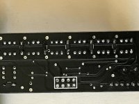
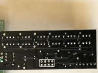
Can't barely see anything on your pictures.
The cathode mark (dash) of the diode should point towards the (+) side of the relay.
Both +5VDC inputs are interconnected on the VoICB at least on my black sample of the VoICB. That is the reason I only use one for feeding it.
The cathode mark (dash) of the diode should point towards the (+) side of the relay.
Both +5VDC inputs are interconnected on the VoICB at least on my black sample of the VoICB. That is the reason I only use one for feeding it.
Last edited:
I removed the Volcb from the BPBP and have attached the picture. Also, when I attache just the 5v and ground, the LED on the Maya is still lit. Only when I attach everything else. In addition, there is continuity between the two 5v pins on the Volcb. Is it supposed to be this way?
Bao
Are you sure all signals are connected correctly, i.e. SDL,SDA, GND and +5V ??
I suspect your PCA9544's. Either they are not compatible, making some short circuit or they are blown.
In any case, the Led on the Maya should stay on at all time.
And is your 5V supply strong enough?
Hans
looking at the specs of the PCA9544 and PCA8574 they are pin compatible and PCA9544 is capable of enough current to drive relays. The only question is if the control code is also compatible. So far I see that I2C slave address setting seems to be different.
Wrong one
Looks like I ordered the wrong one. For the Maya transformer, I'm using a 6.3v @4amps. Is this enough? One more thing, when I just connected the 5v and ground, the LED on the Maya was on but was noticeably dimmer than when it was not connected. I also made sure all the wire connections were correct.
Mouser has 2.471 of the PCA8574 in stock ???
Looks like I ordered the wrong one. For the Maya transformer, I'm using a 6.3v @4amps. Is this enough? One more thing, when I just connected the 5v and ground, the LED on the Maya was on but was noticeably dimmer than when it was not connected. I also made sure all the wire connections were correct.
I have a question about those VoICB => GND connections on the BPBP.
Could I combine those two GND (left/right) from the VoICB and connect them to a more accessible GND position on the preamp board because I had my BPBP build already and those net ties 4/10 are hard to reach and very small to solder to. I hate fiddling around there and might even damage something doing it...
What would be those arguments against doing it ?
PS.: On the Maya control board the BlueTooth module is afixed to the main control board by one singled sided rather loose pin header connector and tilting easily. Any reason for this and not having it afixed on the other side of the small PCB too ?
Last edited:
I told the Forum a long time ago about this and to solder in Tie points early in assembly.............. because I had my BPBP build already and those net ties 4/10 are hard to reach and very small to solder to. I hate fiddling around there and might even damage something doing it.................
Close up
Would you happen to have a close up of what you did? Thank you!
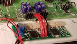
I scraped off a bit of lacquer on the bottom ground plane close to the edge/pot connectors. There was no ill effect from grounding that way. Including no measurable problems.
Would you happen to have a close up of what you did? Thank you!
I told the Forum a long time ago about this and to solder in Tie points early in assembly.
I know, but this isn't really helpful, because I built my BPBPs some time before I decided upon the type of volume controllers I would try.
Would you happen to have a close up of what you did? Thank you!
The net ties 4/10 as GND connections are very close together, about 20 mm (?) apart and connecting to the same GND plane. The question arises, if it really makes any difference to use a (common ?) GND for both channels at this point but easier accessible. Nobody seemed to have questioned this before...
If you look at the picture "ergo" provided, you can see the GND connection at the front edge of the BPBP PCB.
I am looking at one of those two remaining solder lugs (to the rear) of the input switch, which are not been used with the VoICB attached, within the solid GND plane, which could i.e. easily be converted to a connection point for this purpose.
Would that make a noticeable / measurable difference ? Anyone ?
Would that make a noticeable / measurable difference ? Anyone ?
I checked the unused solder lugs (switch) mentioned and they are connected to the GND plane already. Being a solid GND plane and only low currents flowing the inherent resistance difference between those lugs and the net ties should be (probably) negligible...
Last edited:
...
PS.: On the Maya control board the BlueTooth module is afixed to the main control board by one singled sided rather loose pin header connector and tilting easily. Any reason for this and not having it afixed on the other side of the small PCB too ?
Bluetooth module must be installed outside metalic enclosure (in case you use one), or in an area where trafo or other components do not affect his operation. In order to maximize range and operation, a 3cm area around module antenna must be clear of any component. In other words, you need to place module in an area where will operate correctly and solder four wires from Maya pcb to bluetooth module.
This is the main reason why the module was inserted on a loose pin header.
Regards,
Tibi
Tibi
What about adding an external antena ?, that would make things easy.
Module we use do not provide pigtail connector for external antenna, but you may try to "adapt" one.
Regards,
Tibi
I am looking at one of those two remaining solder lugs (to the rear) of the input switch, which are not been used with the VoICB attached, within the solid GND plane, which could i.e. easily be converted to a connection point for this purpose.
Would that make a noticeable / measurable difference ? Anyone ?
Measurable? unlikely
Noticeable? maybe
From Bruno's document, my understanding is that the point about the balanced design and earths is that you try to make the signal earth connections as close to the corresponding signal connections on the board as possible, hence all the net ties...
... so as to avoid signal earth currents flowing through the ground plane of the board together with earth noise currents from other parts of the circuit, as these have nothing to do with the signal at that point in the circuit
- Home
- Source & Line
- Analog Line Level
- Remote Control for the BPBP