Yep I'm quite happy with the setup. Repeated twice because I forgot my starting current. Bias current does cteep up over an hour or so so I kept tweaking it back and then finally it settled. Easy.
If there's a way to check via R11 more directly then I'm still interested. But I can't accurately measure 6mV.
Pops.
If there's a way to check via R11 more directly then I'm still interested. But I can't accurately measure 6mV.
Pops.
It sounds great! At least the first channel, connected via croc clips to a disposable speaker.
Very very happy and now I know exactly what I need to do to finish.
Heatsink doesn't feel warm at all at low output levels? I expect it will all warm up a bit once I get above 10W.
Conveniently, 0.8mm solid core wire slides very nicely into the standard (Elektor supplied) input headers (audio in) so I am inclined to use this (twisted) to form the connection to the RCA terminals on the panel connector. Instead of coax cable, which is much stiffer and hard to maintain a 90deg bend without straining the ends.
Whatcha think? I cant hear any hissing... but second channel might change this.
Pops.
Congrats Pops! And yes, this amp does sound great.
As you've seen during the coarse of this thread, I'm using a 2U enclosure. The heatsink don't get very warm even at higher listening levels. That might change when driving it near full power but in a home environnement this is not very likely to happen.
In terms of the signal input; if those solid wires work without any hum then go for it.
Yep I'm quite happy with the setup. Repeated twice because I forgot my starting current. Bias current does cteep up over an hour or so so I kept tweaking it back and then finally it settled. Easy.
If there's a way to check via R11 more directly then I'm still interested. But I can't accurately measure 6mV.
Pops.
I noticed you are still using the stock potmeter (for bias). It's not very easy to accurately adjust the bias current since a very slight movement changes the bias current quite a bit.
If you want to measure the bias current by measuring the voltage across R11 then remove the 47 ohms resistors in the supply leads first.
But as mentioned before, the Elektor instructions work flawlessly. I even have checked the current over the emitter resistor after adjusting the bias by means of the Elektor instructions and guess what? Yes exactly 30mA. Rest asure, the Elektor instructions are safe and correct.
Yep I had already soldered the pot months ago. I used a more accurate vishay multiturn pot for the second channel, but I did not find the pot too much trouble. I had to spend 10 mins whittling a wooden stick to do the tweaking - definitely not a good place for metal precision screwdriver.I noticed you are still using the stock potmeter (for bias). It's not very easy to accurately adjust the bias current since a very slight movement changes the bias current quite a bit.
If you want to measure the bias current by measuring the voltage across R11 then remove the 47 ohms resistors in the supply leads first.
Also as Andrew has said the bias could comfortably be set much higher, possibly should be set much higher so I figured that whether I end up with 30 mA or 32 mA is really insignificant.
I'll use the higher precision pot on the second channel just to try and match the first channel but it's pure vanity I'm sure.
Pops.
R10 and R11 are the emitter resistors (post6 .pdf).
Since the Qwatt instructions tell you to increase the current by 30mA to bias this amplifier, you will be able to measure 60mVre across 0r2
But have you fitted 0r2, or did you fit 0r22?
If 0r22 is fitted, then the voltage across one will be 66mVre and 132mVre2 across both.
Send me back to school. I promise to listen next time !Thanks Andrew.
Is this correct? 60mV or 6mV?
Pops.
The worst dissipation for a ClassAB output stage is ~ 35% of maximum power.Congrats Pops! And yes, this amp does sound great.
As you've seen during the coarse of this thread, I'm using a 2U enclosure. The heatsink don't get very warm even at higher listening levels. That might change when driving it near full power but in a home environnement this is not very likely to happen.
In terms of the signal input; if those solid wires work without any hum then go for it.
That is ~ -10dB relative to maximum power and some listeners listen at that average level.
i.e. average levels @ ~-10dB ref. max. will make the amplifier hotter than any other operating condition.
you can measure over the two series connected resistors. Then you are measuring 12.0mVreYep I'm quite happy with the setup. Repeated twice because I forgot my starting current. Bias current does cteep up over an hour or so so I kept tweaking it back and then finally it settled. Easy.
If there's a way to check via R11 more directly then I'm still interested. But I can't accurately measure 6mV.
Pops.
That gives you a resolution of better than 1%
As fellow Q-Watt constructor Delange said, replacing the pot to the one he used or similar, the 30mA Q.Current can be set up very slowly and accurately to this value. It's so much easier.
Don't complicate your life popchops
Don't complicate your life popchops
Last edited:
We yet had the bias discussion some weeks ago. Either way works, I'd say. I'd definitely prefer measuring the voltage over both emitter resistors (i.e. between both power devices' emitters) and adjust to 120 mV (@ 0.2R each) or 132 mV (@ 0.22R each), respectively.
Best regards!
Best regards!
Post #35 explains about a better pot to adjust the Q.Current, i have these fitted in both my Q-Watt's and the Q.Current was very smoothly adjusted to 30mA, using the way its written in the article, so straight forward and precise too.
As previously mentioned the component list shows those resistors as 0.2Ω 1% 5W, low inductance (Vishay Dale LVR05R2000FE73), and come as such in the supplied kit.
As previously mentioned the component list shows those resistors as 0.2Ω 1% 5W, low inductance (Vishay Dale LVR05R2000FE73), and come as such in the supplied kit.
Either way works, I'd say. I'd definitely prefer measuring the voltage over both emitter resistors (i.e. between both power devices' emitters) and adjust to 120 mV (@ 0.2R each) or 132 mV (@ 0.22R each), respectively.
Hi Kay! How is your build?
At the risk of re-opening the worm-can
Both emitter resistors = 0.4R (unchecked). 120mV / 0.4R = 0.3 Amps. Thats 10x higher than I expected? Why would you use such high bias current. What's your reference / background info? Are you getting this from the chip specs?
I was able to listen last night through decent speakers but still using my (low power) mobile phone as a crappy analogue source. Phone glitches are scary. Cannot use my 2.3V DAC without dropping the voltage... even on the lowest digital setting the volume is too loud!
Have been eating a lot of biscuits to free up a tin for a passive preamp.
Pops.
Both emitter resistors = 0.4R (unchecked). 120mV / 0.4R = 0.3 Amps. Thats 10x higher than I expected? Why would you use such high bias current. What's your reference / background info? Are you getting this from the chip specs?
I would stick to the 30mA. There is a section in the Elektor article that says:
Slowly turn P1 to the right (clockwise) until the current increases by 30 mA (60 mA total). This relatively low quiescent current is more than adequate. The quiescent current will rise slightly as the heatsink temperature increases. However, it will normally remain below 90 mA. At very high output power levels, the junction temperatures of the two output transistors will rise much faster than the temperature of the heatsink, so the quiescent current transistor will not be able to fully track the change. This causes the quiescent current to rise briefly to several hundred milli-amps, but it declines quickly when the temperature drops again.
Using a (much) higher bias current will probably kill the amplifier while playing at very high output levels.
I would stick to the 30mA. There is a section in the Elektor article that says:
Slowly turn P1 to the right (clockwise) until the current increases by 30 mA (60 mA total). This relatively low quiescent current is more than adequate. The quiescent current will rise slightly as the heatsink temperature increases. However, it will normally remain below 90 mA.
Aaah delange I think I made a mistake. When I read this I thought it was saying trim back towards the 60mA as the heatsink warms up... but now it seems to me like I should have set the +30 mA once when cold and then just monitor it as it warms up.
I have trimmed for 30 mA in the warm condition, so this is too low?
Thick skull takes some getting through to...
Pops.
Popchops please please stick to the voices of fellow Q-Watt builders.
In the case of Delange and myself our Q-Watt's were set up as per the Elektor explanation in their article.
Please don't create unwanted problems using other formats.
In the Elektor article, as Delange very rightly states , the Q.Current has to be set to 30mA, therefore the total will be 30 on the + rail and 30 on the - rail.
As mentioned already with the other type of preset, the adjustment is set so smoothly, I got mine smack on 30mA
Last edited:
The Elektor method as interpreed by Calpe is completely wrong.
The Elektor method as quoted in this Thread is at best ill advised.
Set the output bias current properly and monitor how it behaves during warm up, before you attach any expensive load.
The Elektor method as quoted in this Thread is at best ill advised.
Set the output bias current properly and monitor how it behaves during warm up, before you attach any expensive load.
From memory, I was getting different currents on pos and neg rail.
And when you say 30mA do you think this is what Elektor expects initially (cold) or after 30-60 mins when temperature has stabilised? Re-reading the instructions it seems like we should expect +30 mA cold and up to +60 mA after warmup.
And when you say 30mA do you think this is what Elektor expects initially (cold) or after 30-60 mins when temperature has stabilised? Re-reading the instructions it seems like we should expect +30 mA cold and up to +60 mA after warmup.
Aaah delange I think I made a mistake. When I read this I thought it was saying trim back towards the 60mA as the heatsink warms up... but now it seems to me like I should have set the +30 mA once when cold and then just monitor it as it warms up.
It is a good idea to monitor the bias as the amp "warms up".
After the initial adjustment leave the amp on for about 15 minutes (without playing music). After about 15 minutes re-check the bias; it should still be more or less 30 mA.
I have trimmed for 30 mA in the warm condition, so this is too low?
What does "warm" mean?
Just power up the amp and leave it on for a while without playing music and then measure the bias. If it's around 30 mA then your good to go.
Last edited:
Re-reading the instructions it seems like we should expect +30 mA cold and up to +60 mA after warmup.
The confusion is probably due to the way the Elektor adjustment process works:
With P1 completely to the left (lets call this 0mA bias) the amp is drawing about 30 mA from the positive supply lead. This current is mainly the relay.
Next, you need to turn P1 so that you add 30 mA to the above situation, meaning 60 mA in total. This is 30 mA bias and 30 mA from the relay.
The Elektor method as interpreed by Calpe is completely wrong.
The Elektor method as quoted in this Thread is at best ill advised.
Set the output bias current properly and monitor how it behaves during warm up, before you attach any expensive load.
Clearly we have elite experts in this field who haven't even build the Q-Watt and have so may unwanted unvalued views, going out of their way to confuse.
Interpreted by me? Well clearly you've build the Q-Watt and know from on hand experience what to expect. Well your wrong!
If the elite experts have doubts write to Elektor for their views.....and as you haven't read the full article.
If you've built the amp, you read the exact setting up procedure as stated by Elektor and not Tom, Dick, Harry and especially not Andrew!
You only go out of your way to confuse matters, so as you haven't build this amp, keep out!
My Q-Watt was placed in my hands as well as my life!
My Q-Watt runs perfect, sound quality tops, no hiss, no feedback, no this and no that.
As a Professor, put that in your pipe and smoke it away at your leisure! Mind you don't choke!
Last edited:
Clearly we have elite experts in this field who haven't even build the Q-Watt and have so may unwanted unvalued views, going out of their way to confuse.
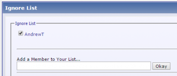
Hi Calpe, there is a great feature on this forum. It is called the Ignore List.
You find this in the User CP -> Settings & Options -> Edit Ignore List.
See the attached picture for the details.
Works like a charm and you don't have to waste your breath on those "smart people". 🙂
Attachments
Last edited:
- Home
- Amplifiers
- Chip Amps
- My Q-Watt project