I did mean the diyAudio spec - "universal" is just what they call it. Your boards were great, by the way.
Manly-Man Trafo Outside Test
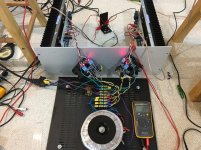
I found the easiest way to put the toroidal trafo outside was to unscrew the heatsinks from the bottom base panel of the amp case, the flip the heatsinks out, thereby doubling the distance of the signal traafo from the original position.
Drum roll....
It works now - helps immensely as the hum is barely audible with ear 3in away from woofer.
Measurement of output noise was 2.2mV before, now it is 0.7mV, very close to the factory spec of 600uV.
There is a reason Mr Pass covers the trafo in a steel shield and puts the signal trafo in a mu-metal box. It is absolutely needed if you dislike hum. Or just use a SMPS and not have it.
Further proof of EM field reduction was provided by measurement of the magnetic field (axis left to right horizontal looking at amp from front ot back) using a Lutron EMF 822A field tester. Original signal trafo location measured 34mGauss. With power trafo outside it is 0.3mGauss in same axis. On axis front to back it went from 12mGauss to 3.5mGauss.
So I think despite the naysayers who thought I had a ground loop due to poor PSU grounding topology, the problem has been the EMI field pumping the signal trafo full of line hum.
Attachments
I found the easiest way to put the toroidal trafo outside was to unscrew the heatsinks from the bottom base panel of the amp case, the flip the heatsinks out, thereby doubling the distance of the signal traafo from the original position.
Drum roll....
It works now - helps immensely as the hum is barely audible with ear 3in away from woofer.
Measurement of output noise was 2.2mV before, now it is 0.7mV, very close to the factory spec of 600uV.
There is a reason Mr Pass covers the trafo in a steel shield and puts the signal trafo in a mu-metal box. It is absolutely needed if you dislike hum. Or just use a SMPS and not have it.
Further proof of EM field reduction was provided by measurement of the magnetic field (axis left to right horizontal looking at amp from front ot back) using a Lutron EMF 822A field tester. Original signal trafo location measured 34mGauss. With power trafo outside it is 0.3mGauss in same axis. On axis front to back it went from 12mGauss to 3.5mGauss.
So I think despite the naysayers who thought I had a ground loop due to poor PSU grounding topology, the problem has been the EMI field pumping the signal trafo full of line hum.
Well, sometimes. I used Antek, 18+18 @500VA inside a 4U. No shirld on transformers, no Mu metal boxes over small transformers and it is quiet. Very odd these hum problems, glad you figured it out. Such a fine amp.
Russellc
Transformer noise is highly variable,
even among the most respected brands.
It must be, and even from the same supplier. Zen Mod once mentioned that if having a custom one made, to have it made on a core for a larger VA model. For instance, if you wanted a 300 VA model, have it made on a core normally used for say, a 400 VA unit.
For my first watt builds with single transformer, I typically have used Antek 18+18 @ 500 VA. At first I feared the stouter transformer might be more of a problem, but this hasnt proven to be the case. Was wondering if for reasons Zen spoke of it was quieter, or did I just get lucky?
Russellc
point of having custom made is number of windings/volt , thus lesser flux
that's nothing to have with using overkill sized xformer ..... be it 300 or 500VA , all regular ones are made by regular calculus
that's nothing to have with using overkill sized xformer ..... be it 300 or 500VA , all regular ones are made by regular calculus
Zen Mod once mentioned that if having a custom one made, to have it made on a core for a larger VA model. For instance, if you wanted a 300 VA model, have it made on a core normally used for say, a 400 VA unit.
Russellc
Not just a larger VA model is important; more important is to have the transformer wound with a low core excitation.
As 1.6-1.7T is pretty normal for off the shelve transformers, have the custom one wound for some 1 T of core excitation.
Potential problems like resonances, strayfields and sensibility to peak line voltages (causing core saturation) are killed at the source that way.
Low core excitation transformers require larger VA models as more primary turns are needed on a given core for this low T.
And don't forget to specify a screen between primary and secondary.
Last edited by a moderator:
xrk, how sensitive is your scope?
Can you show traces of the amp's output with transformer in and out?
Can you show traces of the amp's output with transformer in and out?
That's one thing I wanted, (the screen) but it wasnt available at the time. For the F5 I built, which was my first diy Pass build, I used two 18+18 300 VA transformers (Antek) and had silent results. I hope something hasnt changed with there construction. Such a bargain for these amps.Not just a larger VA model is important; more important is to have the transformer wound with a low core excitation.
As 1.6-1.7T is pretty normal for off the shelve transformers, have the custom one wound for some 1 T of core excitation.
Potential problems like resonances, strayfields and sensibility to peak line voltages (causing core saturation) are killed at the source that way.
Low core excitation transformers require larger VA models as more primary turns are needed on a given core for this low T.
And don't forget to specify a screen between primary and secondary.
Russellc
I have used the Antek 400 VA transformers with the built-in screening for several Pass builds and have had zero noise problems. I'm really enjoying my M2, at first it didn't play well with an Aikido preamp, so I built a Salas preamp, wow what an improvement, great combo.
I have used the Antek 400 VA transformers with the built-in screening for several Pass builds and have had zero noise problems. I'm really enjoying my M2, at first it didn't play well with an Aikido preamp, so I built a Salas preamp, wow what an improvement, great combo.
The M2 was such a nice gift for our diy community! One of the best sounding, yet easiest to maintain and build. I really enjoy mine.
Not sure why it hasnt made it to the diy store, its a natural.
Russellc
Pass M2
Agreed!!!
The M2 was such a nice gift for our diy community! One of the best sounding, yet easiest to maintain and build. I really enjoy mine.
Not sure why it hasnt made it to the diy store, its a natural.
Russellc
Agreed!!!
The M2 was such a nice gift for our diy community! One of the best sounding, yet easiest to maintain and build.
+1
Has someone tried to configure the signal transformer as a 1:5 step up transformer instead of wiring it as an autoformer.
In that case C2 can be omitted.
Just curious as it could be done easily.
In that case C2 can be omitted.
Just curious as it could be done easily.
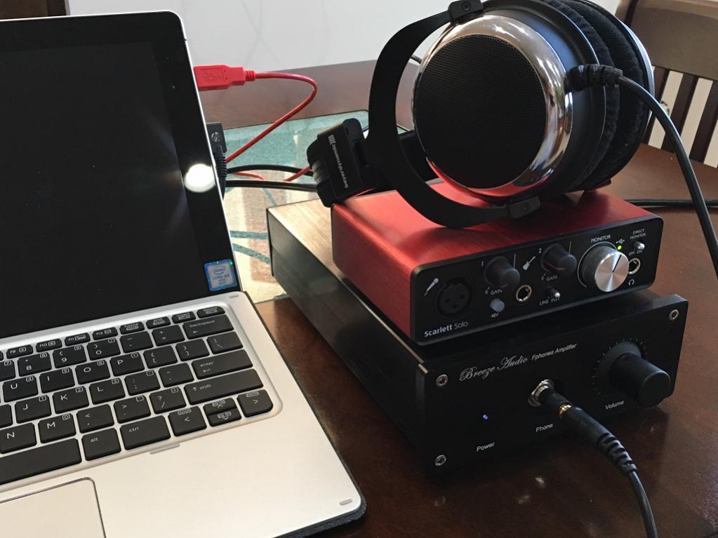
I really did not like the sound from mine until it had a proper SE Class A preamp. I use this headphone amp as my preamp.
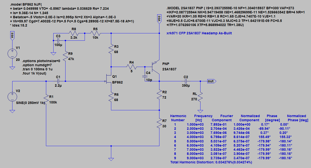
This is the core of the preamp:
But together - the synergy of these two amps is amazing.
This is the core of the preamp:
But together - the synergy of these two amps is amazing.
Last edited:
Has someone tried to configure the signal transformer as a 1:5 step up transformer instead of wiring it as an autoformer.
In that case C2 can be omitted.
Just curious as it could be done easily.
not so trivial to establish DC free input node at mosfet gates side, without spoiling optocoupler's function
and , it would demand more expensive iron , at least as I'm understanding that autoformer is less critical to make than xformer , in same league of transfer characteristics
I really did not like the sound from mine until it had a proper SE Class A preamp. I use this headphone amp as my preamp.
This is the core of the preamp:
But together - the synergy of these two amps is amazing.
Mine is used with Pearl 2 and BA3 FE. Eventually, pre will be Pumpkin Shunty, (at least until I have more balanced components) which is on temporary hold while my other hobby's builds have taken my time and $$$.
Russellc
Last edited:
Zen Mod, you mean possible DC between R2 and R3?
The autoformer is "easier" to reach HF bandwidth, but on the other hand it will have rather severe resonances at frequencies above 20 kHz: the Zobel network across the autoformer is necessary.
The autoformer is "easier" to reach HF bandwidth, but on the other hand it will have rather severe resonances at frequencies above 20 kHz: the Zobel network across the autoformer is necessary.
ref. to schm in post #1 , you need to establish driving node anywhere between upper and lower gate , driven through low enough impedance chain
so , to fully exploit xformer and galvanic isolation , thus avoiding series cap , it seems logical to tie one end of secondary to GND , and other end wherever you can establish DC free point ;
or , to tie one end of secondary to chosen point at mosfet gates side , and other end to deliberately made same DC potential point , also having low impedance to serve as modulation reference .........
I can't see easy enough way to do it , without spoiling efficiency of optocoupler operation
I hope I am clear enough what I'm thinking ......
- Home
- Amplifiers
- Pass Labs
- Official M2 schematic