
It's apparent that Pao is backwards, and really doesn't like p-channel power devices. (especially the hump-backs)
Hey....that's me you mean!! Poa, backwards that is. It means Old Age Pensioner......you cheeky young dutchie whippersnapper.

AND, although I am not as straight statured as I was , but am NOT (yet) a hunchback!
😀😀😀
well - something like this
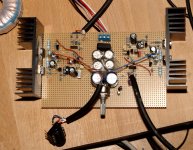
I built this headphone thing - with 2SK389 and reversed polarity, and reduced R13 to 22k for 300 mA.
Problem: it is humming which gets worse when I plug in any input, balanced or unbalanced. Any idea?
Sound is great as far as one can tell with a background hum ...
You mean images?
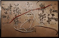
(The pot is not connected)
What would you think is the minimum supply capacitance? Maybe these caps are old...
Supply ripple is 0.5 V
(The pot is not connected)
What would you think is the minimum supply capacitance? Maybe these caps are old...
Supply ripple is 0.5 V
Attachments
Last edited:
CRC of 10mF-0R1-10mF per rail , will do the job for stereo
Ok done this and the hum is nearly gone, practically it is ok.
Any suggestion how to connect a volume pot? I tried one shorting the + and - inputs but makes it really hum ...
Code:
gate - 1k - pot pin - 22k - input+
            0..100k
gate - 1k - pot pin - 22k - input-click on this: PSM LS Cook Book , in my signature , then you'll know more about attenuator wiring
If I turn the pot down the output DC rises
Unmatched output FETs?
two things for setting Iq and output offset :
- ground inputs
-no load on output
if attenuator is connected properly , no change in output offset
I wanted to avoid a quadruple pot, and electronics ...
I moved the pot to before the 22k and added 16k before that. Working well, no hum. Change of offset is a few mV now.
Sound is so far very nice, probably can be tweaked ...
Thanks 🙂
I moved the pot to before the 22k and added 16k before that. Working well, no hum. Change of offset is a few mV now.
Sound is so far very nice, probably can be tweaked ...
Thanks 🙂
I do not have VR 47Ohm. So I can replace. and adjusting VR1 and VR2 ???.
Sorry for bad english .
Sorry for bad english .
I do not have VR 47Ohm. So I can replace. and adjusting VR1 and VR2 ???.
Sorry for bad english
Thank You !!!! .
I'm in Mountain , with wimpy net connection
I'll be back in a week or so ......... then will reply , if nobody chime in
however , according to
use 50R as 47R and 50K as 47K ;matter of local availability
I'll be back in a week or so ......... then will reply , if nobody chime in
however , according to
use 50R as 47R and 50K as 47K ;matter of local availability
I just start the artwork for the pcb on the Babelfish J with input SJ109BL (because I have some).
I also have a lot of 0.47 Ohm/5W resistors. Would there be an easy way to calculate the needed R- value with a given voltage and Iq and so the output wattage or other way around?
Or in other words: I like to use these resitors and my max. power should be 25-30 W, so which voltage and Iq I have choose?
I guess you can use the design as-is and just use a parallel pair of 0.47 ohm resistors
where you see 0.22 ohm ones. The differences should not be large.
where you see 0.22 ohm ones. The differences should not be large.
- Status
- Not open for further replies.
- Home
- Amplifiers
- Pass Labs
- Babbelfish J PCBs