I just start the artwork for the pcb on the Babelfish J with input SJ109BL (because I have some).
I also have a lot of 0.47 Ohm/5W resistors. Would there be an easy way to calculate the needed R- value with a given voltage and Iq and so the output wattage or other way around?
Or in other words: I like to use these resitors and my max. power should be 25-30 W, so which voltage and Iq I have choose?
you're going to use IRFP150?
meaning - one output pair ?
Jap, I´m using the IRFP150, and your schematic from http://www.diyaudio.rs/choky/Babelfish J.html....
35 years ago when I built my first amp I learned, that for an "acusticly" good room you only need about 1 W per sqm. How true. So this time also I do not want to build an overkill either. Small case, less heat, a nice little package.
And I like to use the parts I allready have.
35 years ago when I built my first amp I learned, that for an "acusticly" good room you only need about 1 W per sqm. How true. So this time also I do not want to build an overkill either. Small case, less heat, a nice little package.
And I like to use the parts I allready have.
feel free to use your fave 0R47 as biggie resistors , if you are satisfied with Iq up to 0V65/0R47=1A38
stay with regular FW PSU - based on 2 x 18Vac secondaries ( F4 manual at FW , for instance , is having nicely drawn one) , resulting in approx. 22.5Vdc rails
if you want more than 1A38 per IRFP150 vertical pair , then just double (parallel) your 0R47 resistors in all positions (both source and sense resistors , in short - all 0R27 drawn here )
I believe then you'll be able to set precise Iq with trimpot , trowing no more than 50W of heat through each ..... and that would be around 2A for Iq
under condition that htsnks (mosfets through mica and white drek , or better) are in comfort zone - up to 55C in summer time
if needed , make Babysitter
Attachments
Last edited:
Well Zenmod, that´s the answer I was looking for. Thanks.
So with 22,5 V and 1,38 A I get 31,05 Watts trough des IRFP150, with 0,27 Ohms its 2,4 A, resulting in 54,2 Watts.
Understood (hopefully)....
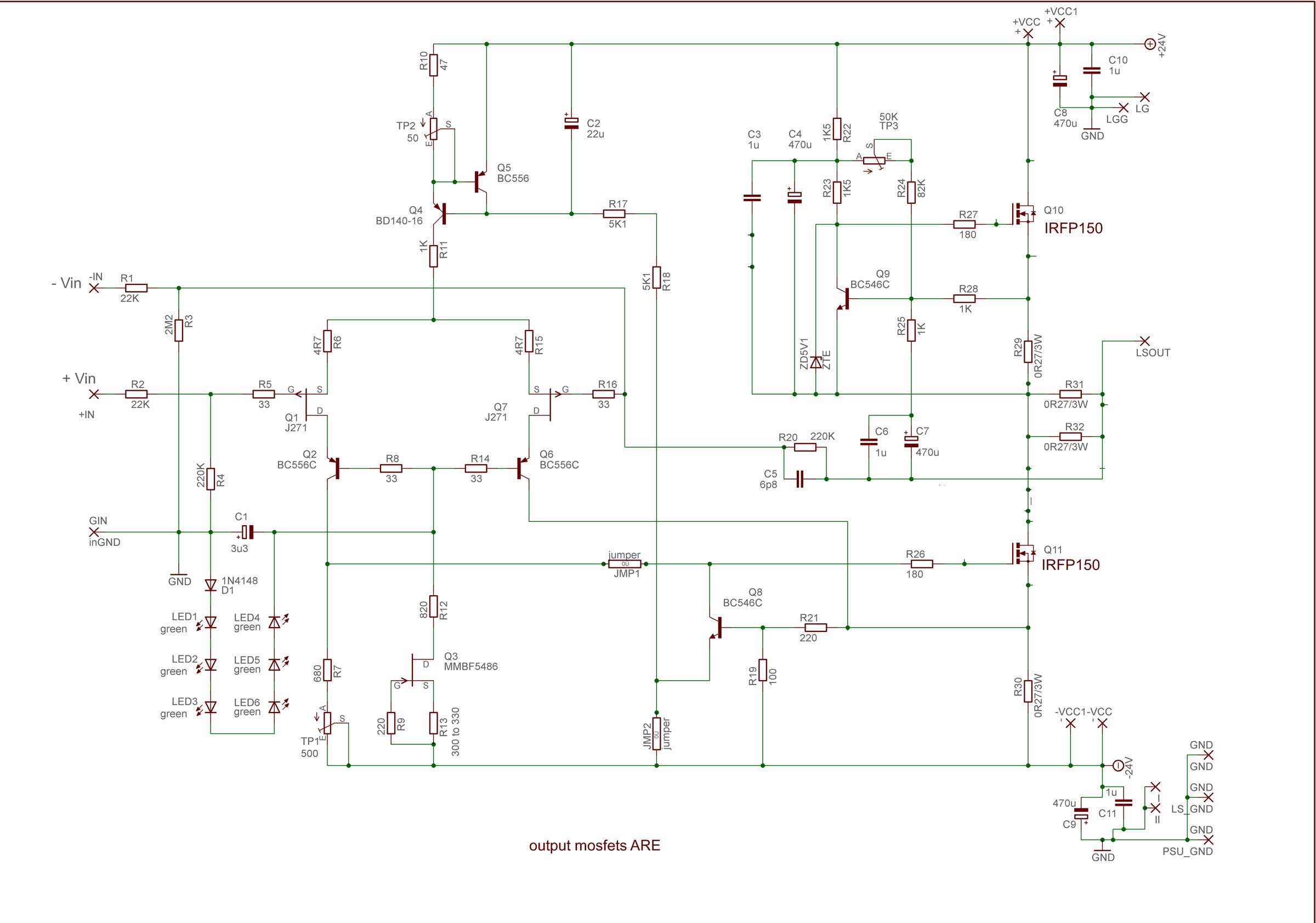
What is the purpose of R22/R23 in this diagram, would be my last question.
So with 22,5 V and 1,38 A I get 31,05 Watts trough des IRFP150, with 0,27 Ohms its 2,4 A, resulting in 54,2 Watts.
Understood (hopefully)....
What is the purpose of R22/R23 in this diagram, would be my last question.
I just bought some IRFP150's. I also have a bunch of the nice light blue Panasonic 0.47R 3W resistors and was wondering the same thing about using them. Seems Ok. I can definitely handle 60W on my heatsinks and probably even a bit more as they were not that warm at 60W.
What is advantage of 150's over 240's?
The above schematic is very different than this one which the board I have from this thread:
What is advantage of 150's over 240's?
The above schematic is very different than this one which the board I have from this thread:
Last edited:
it's not that different ;
just showing my later developed addiction to green LEDs
look at IRFP150 as two IRFP240 in single package
just showing my later developed addiction to green LEDs
look at IRFP150 as two IRFP240 in single package
I do have a question about C7: it is connected to the feedback and the CCS MOSFET circuitry - you recommend the best audio grade cap, like a Silmic II etc. be used here. In what sense does the audio signal pass through here since it is going to the CCS?
everything pretty much explained in Aleph CCS patent - entire series of amps got name from that
lower mosfet is commanded by input LTP , directly amplifying input signal , then current goes to ldspk through small resistance ( biggies connected in parallel) , then voltage sag across them is directly used (through C7 and C6 and R25 ) to modulate Aleph CCS
what is nice and clever there ...... modulation of Aleph CCS is pretty much dependable of nature of load ...... I mean loaaaaaadspeeker
patent ; go here and paste this number : 5710522
for C5 - buy biggest SMD , solder pins on it , then solder on pcb
or solder it on copper side directly
nice looking .....
or solder it on copper side directly
nice looking .....
Yes I have done that trick before. It's just that my smallest NP0 SMT is 22pF. I need to order some small values.
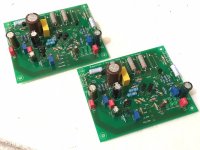
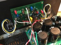
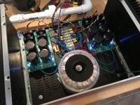
PSU with 400VA trafo and dual Prasi/Project16 CRC Class A PSU's finished and working. 1mV ripple with zero load:
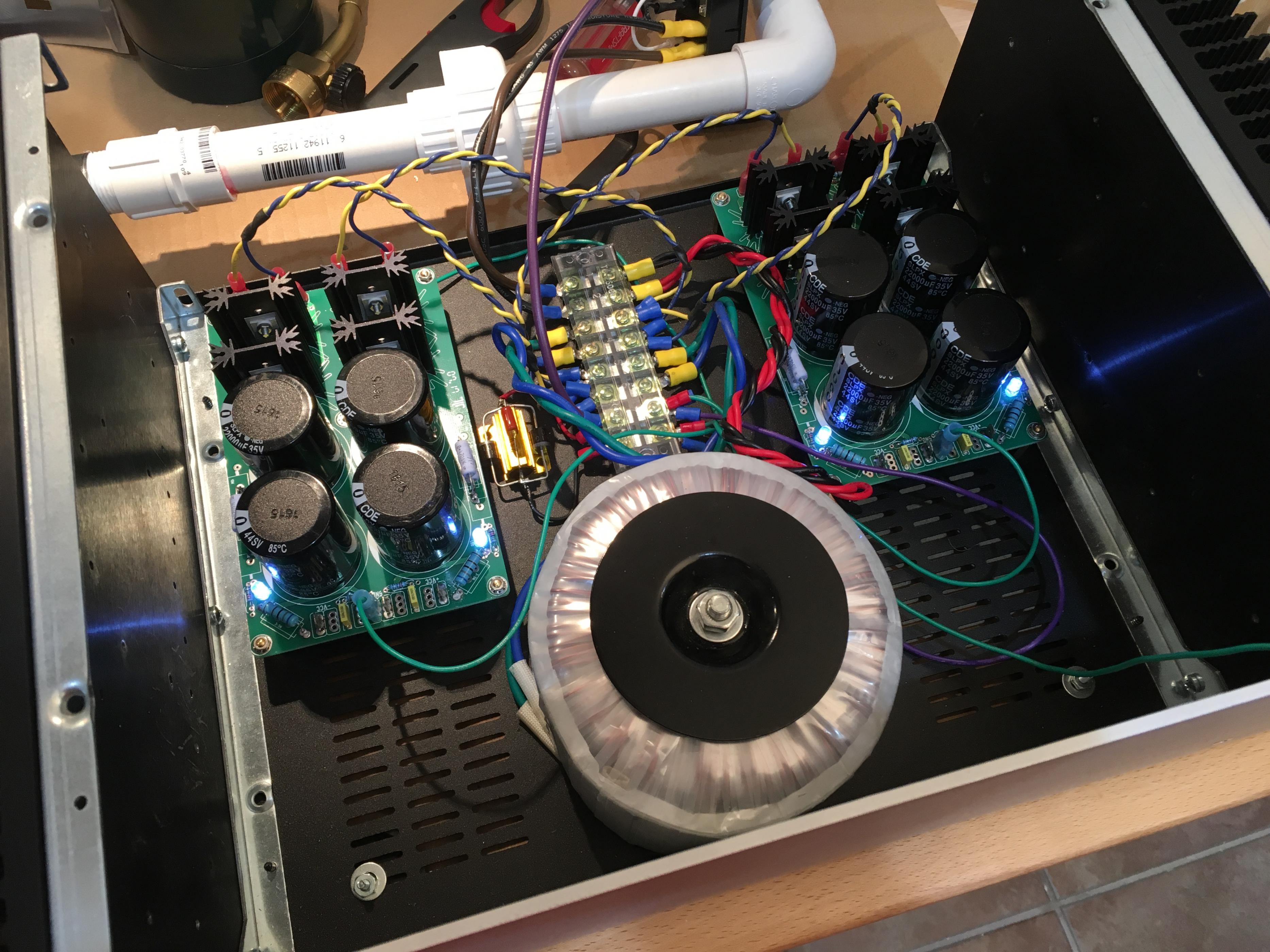
The Babelfish J PCB has screw holes that fit DIYA UMS heatsink (3 screws perfect). However, MOSFETs have to be flying leads and offboard. Getting closer:
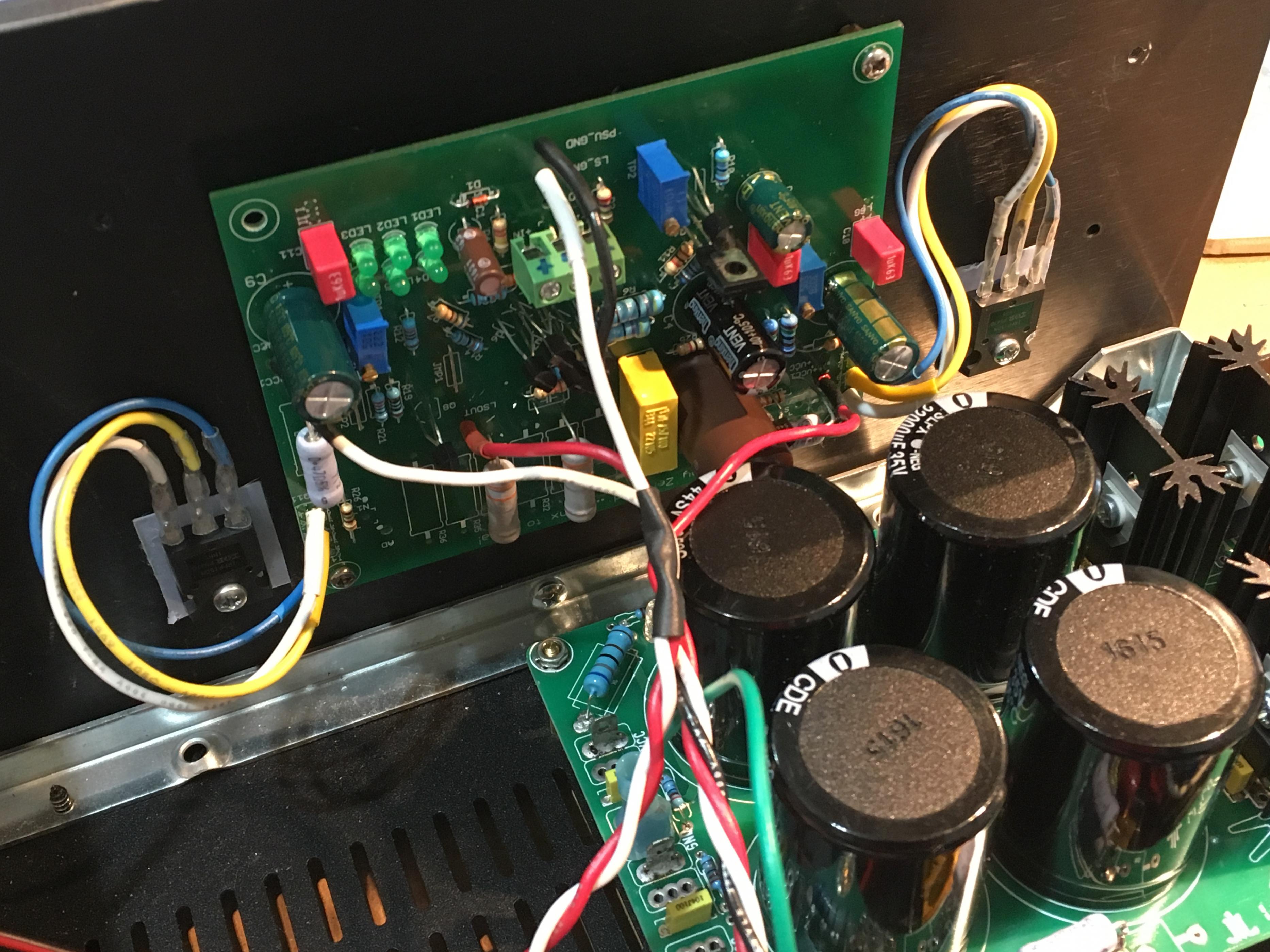
C5 is now made by putting qnty 3 x 22pF NP0 0805 caps in series and soldered directly to bottom side between two pins. 7.3pF should be close enough. I guess the voltage rating actually goes up 3x with caps in series?
The Babelfish J PCB has screw holes that fit DIYA UMS heatsink (3 screws perfect). However, MOSFETs have to be flying leads and offboard. Getting closer:
C5 is now made by putting qnty 3 x 22pF NP0 0805 caps in series and soldered directly to bottom side between two pins. 7.3pF should be close enough. I guess the voltage rating actually goes up 3x with caps in series?
Attachments
Last edited:
What are the odds of those corner screws being spot on? I was lucky because that saved me from drilling and tapping.
Can you remind me where the startup sequence was posted? Why are there 3 pots?
Thanks,
X
Can you remind me where the startup sequence was posted? Why are there 3 pots?
Thanks,
X
completely other thread 🙂
better to go there - ( in fact , you've been there ) : About possible Babelfish J interest
let me know do you need more info ..... forgot what's written
better to go there - ( in fact , you've been there ) : About possible Babelfish J interest
let me know do you need more info ..... forgot what's written
- Status
- Not open for further replies.
- Home
- Amplifiers
- Pass Labs
- Babbelfish J PCBs