Richard: I meant the picture I posted. If you look at the cantilever you can see a thin bit with the moving iron in and a fat bit which is the pivot (at least in this DJ cart). If you then squint at the second picture you can see the fancy asymmetric bearing and behind that what I assume is the damper. So you have two things you can vary. But if you move the resonance up and leave high damping at (say) 15kHz you would potentially end up with a dip. This may not matter and is correctable, but good to get an idea of what matters.
Charlie: Very interesting, please don't lurk as would love to learn more about your conclusions on this.
On the temperature front, I wonder why no one has glommed a peltier element on a cartridge yet as a feature!
Charlie: Very interesting, please don't lurk as would love to learn more about your conclusions on this.
On the temperature front, I wonder why no one has glommed a peltier element on a cartridge yet as a feature!
Thanks for the insights, Charlie
Thanks for recounting endeavours from times past! You reminded me of running "strange" FORTRAN decks (personal jobs) overnight, after the regional government payroll had been completed and CPU demand was low ... collecting the printout in the morning with high probability that I'd be reading a short, cryptic CPU dump rather than a long and successful printout ...
If you have ready access to your early work, I'd like a little guidance (or ideally a walk-through!) of your cantilever-to-transmission line transform, and your thoughts on translating the boundary conditions to suitable impedances. I'd settle for any crumbs, analytic and/or the empirical, or any marriage of the two.
That aside, I am more and more drawn to the experimental approach - a calibrated piezo transducer to excite the stylus with the cartridge mounted in the tonearm to give something like a very broadband output response. Then kgrlee could farnarkle a digital RIAA transform on a cartridge-by-cartridge basis (let's hope the channels match ...).
Seriously, the experimental approach could deliver some interesting results, as well as honour the skill and craft of cartridge designers.
Thanks for an interesting post, Bondini.With the caveat that I would really like to find the paper containing those charts, I have some thoughts to offer.
Those charts crop up in a couple of papers IIRC, one of them is here:
Dynamic Modeling and Analysis of A Phonograph Stylus, Lawrence R Happ, Shure Bros Inc
JAES 1979 Jan/Feb Vol 27 No 1/2
JAES 1979 Jan/Feb Vol 27 No 1/2
PM me if you don't readily find it.
Yes, perhaps, but also see below. Also, the stylus is free to rotate, so is not fully constrained at its support, which modifies wave constants, of course.Happ’s Figure 5 model in Shure’s online technical seminar includes parameters Rw and Vw at the shank pivot that potentially “relax” the pure cantilever constraints. Finagling something similar using the Bernoulli-Euler equations for beam flexure, I get rough-as-guts estimates of wave numbers of the resonant modes at 1.0, 1.8, 3.2 and 4.8 so that, if we take the first mode as being at 20kHz, we get successive resonances at 36kHz, 64kHz and 96kHz – and 36kHz is a lot closer to the Happ/Shibata chart than 125kHz!
A suspension rubber is an elastomer, as you say, and has dynamic visco-elastic properties which probably are typically butyl like. Dynamic impedance for programme material induced motion would probably be mostly damping, which is a good thing IMO. I doubt that the Happ spring and damper quite describes it, and there's an argument that the elastomer is dynamically relatively rigid for the same reason as vinyl might be....... in which case, mostly the suspension would mostly act as a rigid support for a free pivot with some damping, for programme material anyway. But as a spring/damper for subsonics, such as cart/arm positional motion. The impedance of a suspension to programme material only affects force required to track, not motion of the generator/linearity of cartridge output, except by flex.If that sort of approach is on the right track, then kgrlee’s “rubber bung” and billshurv’s elastomer grommet become a rather important component. Groh and Van den Hul think so too – and I am inclined to follow their lead, especially on the matter of the frequency dependence of grommet compliance and damping. Yes, there is the tie-wire at the cartridge end of the shank, though I want to treat it solely as a device for holding the pivot point in place relative to the cartridge body rather than an important part of the shank system (which is already complicated enough!).
I think about an order of magnitude stiffer than the cantilever is plausible, IIRC from my previous calculations I predicted it would be between 1 and 2 orders of magnitude. So I could live with 1/8, I think that is suitably negligible in the practical scheme of things. Dominated by cantilever flex is the key.So, having looked at the constraints at one end of the shank (whether modelled by a flexural mechanical system or by transmission-line analog) I turn to the other end, which is where I think that my view parts company with Lucky’s. The Shure comments on vinyl/tip compliance (post #856) and the vinyl ester data (post #858) lead me to believe that incorporating some vinyl/tip compliance is a useful boundary condition to apply at the stylus end of the shank. At one extreme, the constraint could be modelled with zero compliance (I think this is your view, Lucky, pls let me know if I have that wrong) or at some other value that is less than the compliance of the rest of the shank (as in the Shure example, where it appears to be modelled at 1/8th of the compliance of the cantilever assembly).
Here's a repost of TL equations for a cantilever as I derived them a few years back, in terms of physical dimensions and material properties. Note the mechanical transmission line is dispersive - so you'd need to model it with a TL model of appropriate group delay.Equally, I would appreciate anyone’s thoughts on transforming a cantilever with distributed compliance and mass into an analogous transmission line with distributed inductance and capacitance.
Thanks for an interesting post, Bondini.
LD
Attachments

Last edited:
6. Apologies for hijacking this thread at such length. I shall now return to lurking, with hopes the discussions will continue. There’s much to be learned about these confounded talking machines.
Charlie welcome to the forum and thank you for that post.
Larking-only mode from your part will be considered an offensive action and will be punished accordingly (tied on a chair between two loudspeakers, forced to repeatedly listen to the amplified reproduction of a cartridge needle dragged across a vinyl record)
George
Thank you for a very interesting post, Charlie.But what is “high” speed? Agreed there is vinyl indentation at rest: at what linear groove velocity does the indentation become negligible? Perhaps it’s more like surfing than skating? Surfboards leave a wake.
Well, about x 250000 linear dimension of stylus contact region passes beneath the stylus per second. Using surfboard dimensions (esp for Richard 😉 ) playback linear velocity to scale would be about 250km/S, or about mach 700........! This, I think, is a very human way of illustrating that it very probably effectively skates, IMO.
In the skating scenario, there would effectively be a point contact between stylus and groove.
In this scenario, in a modulated groove, the instantaneous contact point would move on the stylus surface, within a 'contact region'. Stylus wear would follow the distribution of time spent in any given contact location, but generally would wear in a way that increased the radius of curvature for all points within the 'contact region', until eventually the region would be polished flat in an elongated oval shape, as the stylus effectively sat progressively lower in the groove. IME, this is what one sees.
LD
That aside, I am more and more drawn to the experimental approach - a calibrated piezo transducer to excite the stylus with the cartridge mounted in the tonearm to give something like a very broadband output response. Then kgrlee could farnarkle a digital RIAA transform on a cartridge-by-cartridge basis (let's hope the channels match ...).
We discussed this back in the beginning of the thread, I think I posted a source of modern piezo actuators that were only $10's of dollars for samples. The problem is calibration, reference piezo accelerometers are very expensive. These have an almost perfect form factor with a self resonance of >400kHz, unknown how much the 1-2g load will lower that. https://www.thorlabs.com/newgrouppage9.cfm?objectgroup_id=10311
Bill, LD - simple experiment let the TT spin down during the 500 - 50k constant velocity test record. You can pick a time with a stopwatch since it is time calibrated. Or you could read a strobe disk with a phototransistor and record it along with a test track while spinning the TT by hand at a small fraction of normal speed.
Last edited:
Another thought experiment. If data exists for stylus wear couldn't there be made an argument based on conservation of energy to estimate the dissociation of the carbon atoms vs. the vinyl molecules?
We discussed this back in the beginning of the thread, I think I posted a source of modern piezo actuators that were only $10's of dollars for samples. The problem is calibration, reference piezo accelerometers are very expensive.
Thanks for the reminder, Scott. I shall consult friends who know a bit about calibrating such things.
Here's an interesting puzzle question type discussion about the wear shape of a hard sphere sliding on a surface. What do we all think ?
https://physics.stackexchange.com/questions/267665/sliding-sphere-wear-shape
Also, I wonder whether Charlie's proposition about surfing isn't more consistent with the nature of observed stylus-groove friction? Which I believe to probably have a strong random element, stick-slip nature, with momentary loss of contact above a certain threshold giving rise to surface noise. I wonder whether variation in vinyl surface composition gives rise to surf depth variations, including momentary lift-off, under certain conditions ?
LD
Looking at the microscope thread on VE and the wear shapes are interesting. Once the stylus gets beyond useful life the wear pattern goes from an ellipse to a tear-drop shape. It's a bad thread as makes me want to buy bits for the camera to measure this 🙂
Thread is here https://www.vinylengine.com/turntable_forum/viewtopic.php?f=19&t=92996
Thread is here https://www.vinylengine.com/turntable_forum/viewtopic.php?f=19&t=92996
But that's an Ortofon. My Jurassic memories are coming up with this on Ortofons.I meant the picture I posted. If you look at the cantilever you can see a thin bit with the moving iron in and a fat bit which is the pivot (at least in this DJ cart). If you then squint at the second picture you can see the fancy asymmetric bearing and behind that what I assume is the damper. So you have two things you can vary.
Your query in #878 was about SHURE cartridges. I was merely pointing out that SHURE seemed to always use a 'single' bung. The extra HF damping was a gob on the end of the magnet and not part of the bung/pivot at all.
Err.rh! The SHURE paper you quote "Dynamic Modelling ..." provides the pic in the seminar web page which distinctly shows the pivot moving around and back & forth.luckythedog said:I doubt that the Happ spring and damper quite describes it, and there's an argument that the elastomer is dynamically relatively rigid for the same reason as vinyl might be....... in which case, mostly the suspension would mostly act as a rigid support for a free pivot with some damping, for programme material anyway.
I don't understand George.gpapag said:What is printed on the vinyl in this track is flat, no RIAA emphasis. See attachments from flat playback.
Are you saying there is NO RIAA emphasis on those tracks?
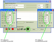
I see you are using a flat preamp for the pics in #873 but how are you doing the FFTs? What programme? What FFT size? Windowing?
And also the curves in #843 though you say these were with an RIAA preamp.
______________
Please excuse my harping on this but its important if we are to dream up an accurate cartridge EQ.
My suspicion, for which I need this info to test, is that we are getting really wonky results on the sweep measurements cos we are using too small an FFT to make sense of a signal which is only 'wideband' if you look at the whole thing. You 'sweep response curves' show too much up & down to make sense.
The earlier pink noise measurements seem more 'sensible' cos even a short section will have 'similar wide band' properties anywhere along the whole track. ie a good candidate for quick response measurements.
Last edited:
Looking on the web for pointers as to the 'skate or surf' question, I came across a branch of physics known as elastohydrodynamics, which seems to address it.
For example, here's an abstract
So I think the topic warrants a bit of reading. I think it describes the surface layer behaviour in a dynamic situation such as vinyl playback. Whether the contact is 'dry', has a lubricant, or becomes self lubricating, the surface layer behaves as a fluid and is subject to elastohydrodynamics. But hey, yesterday I couldn't even spell that, so I look forward to reading on the topic.
I think there's a chance of tying up a few loose ends, such as how does wet playback work, which immediately seems to apply.
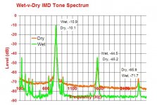
BTW, I noted from my tests a time back that 3rd harmonic distortion can be suppressed by wet playback, but I never understood why. Perhaps there is a connection, further to Scott's questions and the suggestion that 3rd harmonic distortion might be a marker for flex?
All interesting stuff !
LD
For example, here's an abstract
The elastohydrodynamic transition speed for spheres sliding on lubricated rubber
D.F Moore, Wear Volume 35, Issue 1, November 1975, Pages 159-170
Abstract
An elastohydrodynamic number derived elsewhere in the literature [1] characterizes the onset of hydrodynamic support for a rigid sphere sliding on a lubricated viscoelastic base. This number includes elastic properties of the base track, in contrast with previous studies where such have been neglected. A generalized coefficient of sliding friction has been defined as the actual coefficient of friction divided by the tangent modulus of the viscoelastic material. Experimental plots of the coefficient of friction versus sliding speed for spheres sliding on lubricated rubber are shown to produce a relatively sudden decay in coefficient at the transition speed from “dry” to elastohydrodynamic contact. These plots in turn fit closely on a master curve of generalized coefficient of friction versus the elastohydrodynamic number.
The inclusion of surface roughness on the sphere produces both a higher value of the generalized coefficient prior to the transition speed and a higher sliding velocity at which the transition itself occurs. Furthermore, the rate of decay for the generalized coefficient of friction appears distinctly greater for rough spheres. The overall effect of roughness is to reduce the difference between the dry and wet coefficients of sliding friction. Random abrasion of the spheres with emery paper of known grit size appears to be an effective method of inducing surface roughness on the spheres. The nature of all the experimental curves may be satisfactorily explained by squeeze-film theory.
So I think the topic warrants a bit of reading. I think it describes the surface layer behaviour in a dynamic situation such as vinyl playback. Whether the contact is 'dry', has a lubricant, or becomes self lubricating, the surface layer behaves as a fluid and is subject to elastohydrodynamics. But hey, yesterday I couldn't even spell that, so I look forward to reading on the topic.
I think there's a chance of tying up a few loose ends, such as how does wet playback work, which immediately seems to apply.
BTW, I noted from my tests a time back that 3rd harmonic distortion can be suppressed by wet playback, but I never understood why. Perhaps there is a connection, further to Scott's questions and the suggestion that 3rd harmonic distortion might be a marker for flex?
All interesting stuff !
LD
Last edited:
You need to be careful of concluding the reduction of 3rd is due to wet play.BTW, I noted from my tests a time back that 3rd harmonic distortion can be suppressed by wet playback, but I never understood why. Perhaps there is a connection, further to Scott's questions and the suggestion that 3rd harmonic distortion might be a marker for flex?
The SHURE seminar web page has experimental data on repeated playing with different stylii including some cases where THD reduced on subsequent playings.
Walton (DECCA) showed similar results in the early 70s
It shows the generator pivoting about an intended point only, consistent with a rigid support for a free pivot. Which is as I posted, as to how I think support and impedance provided by elastomer suspension for programme material induced motion might work, plus some rotational damping.Err.rh! The SHURE paper you quote "Dynamic Modelling ..." provides the pic in the seminar web page which distinctly shows the pivot moving around and back & forth.
LD
But that's an Ortofon. My Jurassic memories are coming up with this on Ortofons.
Your query in #878 was about SHURE cartridges. I was merely pointing out that SHURE seemed to always use a 'single' bung. The extra HF damping was a gob on the end of the magnet and not part of the bung/pivot at all.
Appears my brain said 'ortofon' and fingers typesd 'shure'. Sorry about that. It was the adjustments that we could do with the second bung that were intriguing me.
It's there with dry playback and supressed in wet playback, reversibly and consistently IME.You need to be careful of concluding the reduction of 3rd is due to wet play.
If it's the one I'm thinking of concerning effects of 100+ plays on wear versus stylus profile versus VTF, the results are all over the place, and IIRC Shure pretty much said as such in the paper. Could be related I suppose........but in any event, that is very different from my tests for wet playback.The SHURE seminar web page has experimental data on repeated playing with different stylii including some cases where THD reduced on subsequent playings.
I found an example of 3rd harmonic suppression with wet playback, attached below, from my tests some time back. The x axis appears to be mislabelled, but one can get the gist I think.
LD
Attachments
Last edited:
Are you saying there is NO RIAA emphasis on those tracks?
Yes Ricardo.
HFN 09 Test disk, Side 2 band 7 (full range frequency sweep, 18s long) is a flat track . No RIAA emphasis.
I see you are using a flat preamp for the pics in #873 but how are you doing the FFTs? What programme? What FFT size? Windowing?
And also the curves in #843 though you say these were with an RIAA preamp.
Correct.
Pics at #873 is from flat amplification.
Pics at #843 is from RIAA amplification.
Both from the same TT/arm/cartridge.
See attachment for the FFT program and settings.
The earlier pink noise measurements seem more 'sensible' cos even a short section will have 'similar wide band' properties anywhere along the whole track. ie a good candidate for quick response measurements.
The pink noise tracks are >1 minute long, maybe that's why they are better for response measurement
George
Attachments
It's a bad thread as makes me want to buy bits for the camera to measure this 🙂
Thread is here https://www.vinylengine.com/turntable_forum/viewtopic.php?f=19&t=92996
Very bad thread (your contact line 😀 )
http://i943.photobucket.com/albums/ad273/rparkhurst/P76_L_A.jpg
George
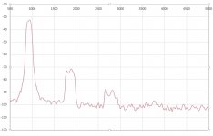
By the miracle of FFT it's possible to extract harmonic distortion data from George's sweep samples for before/after 34hrs rest and relaxation. That's the record, not George BTW 😉
Taking a 0.25s duration aligned sample at 13s, there's a short section of f sweep at about 1kHz, and a swift FFT reveals 2nd and 3rd harmonic distortion arising.
Attached is a plot showing before/after 34hrs between plays, comparing the 10th play with the one 34hrs later. One channel only.
You'll have to look closely, there really are 2 lines........(!) I think this suggests neither 2nd nor 3rd harmonic distortion was affected by 34hrs relaxation, having been played 10 times consecutively before the test.
There's no evidence here of relaxation having any effect at all, rather this appears to confirm 'no effect'. When combined with the overall f sweep result, I think this further evidences there's probably no significant relaxation effect.
One might expect this if there were no meaningful indentation, or very fast recovery, I suppose............
LD
Attachments
Last edited:
- Home
- Source & Line
- Analogue Source
- mechanical resonance in MMs