Because a) the system in vinyl playback is not static and b) there may well be no meaningful deformation in the real dynamic situation.As to the repeat play issue, why can't the elastic deformation and recovery properties be measured statically? Someone must have done it.
No indentation = no recovery...........
There is ample excellent treatment of elastic deformation and relaxation recovery.......implicitly assuming any meaningful deformation exists in the first place!
First one needs to show that meaningful deformation can exist at all, either in theory or in practice, in the dynamic case at hand.
LD
Last edited:
No problem with the Fez.🙂
The first time I watched TV was during the live relay of Apollo 9 landing on the moon.
We had our first B&W TV about 10 years later.
George
I remember the whole family sitting around the TV watching the first moon landing, though it happened several months later here (Apollo 11). 😉
I am sorry. I already have enough proof not to trust my memory for anything.
It was indeed Apollo 11 and here it was a whole neighborhood gathered around a single small (7"? 9" ? )TV
George
It was indeed Apollo 11 and here it was a whole neighborhood gathered around a single small (7"? 9" ? )TV
George
Tonight or tomorrow I will record the 24h+ delayed one
I replayed that track 34h after the last play
>Edit. The ambient temperature during that play was 23.3d Celcius.
here is the wav file (L channel 1st play, R channel play after 34 hours)
https://www.dropbox.com/s/ooga2pzt1no9270/L1st%20R34h%20later.wav?dl=0
George
Attachments

Thank you for doing this George. The recordings are remarkably consistent, which suggests good method for sure.I replayed that track 34h after the last play
>Edit. The ambient temperature during that play was 23.3d Celcius.
here is the wav file (L channel 1st play, R channel play after 34 hours)
https://www.dropbox.com/s/ooga2pzt1no9270/L1st%20R34h%20later.wav?dl=0
George
A swift FFT, looking at channels separately, and I see no meaningful difference between the two recordings of playback separated by 34 hours. Any differences appear within normal Gaussian noise limits, and no trend within a bracket of +/- 0.3dB IMO.
I think this is no surprise, because IMO an f response sweep probably wouldn't show the effect Richard is looking for, which probably doesn't exist in any event.........
LD
I think this is no surprise, because IMO an f response sweep probably wouldn't show the effect Richard is looking for, which probably doesn't exist in any event.........
LD
I agreed in post #860 in advance, I was hoping you would comment on my reasoning re: the 2nd harmonic distortions.
2nd harmonic distortion arises primarily from pinch effect, and affects all styli to some significant extent, and scales with recorded velocity ie programme amplitude.As to LD's comment on measuring distortion rather than frequency response I agree. Intuitively, to me at least, there would be a second harmonic component of stress applied by the stylus which could leave a residual strain with some relaxation time. Unfortunately there is a strong second harmonic distortion due to tracing error with many stylus geometries, so I see this as very difficult to instrument. From that paper the stress/time signature is important in which case I would think the residual strain could be very small.
The effect of flex on distortion, be it cantilever or vinyl (however one sees it!), depends upon the point in the traced waveform when the force at issue is exerted by the groove on the stylus. Historically, much was written about high groove curvature and sine waves in this context, so let's stick with this. High curvature means high programme slew rate, so flex limits slew rate. Distortion arising from this is non-linear, in that it depends on both level and frequency. For a programme sine wave, as amplitude is increased the wave becomes more triangular so gains odd harmonics.
So, at high programme slew rate, eg loud hf but there's more to it than that, I'd look for 3rd harmonic as a marker for flex I think. 2nd harmonic would follow pinch effect mostly.
As to stress/time signature.
I think the proposition is, approximately, a very hard 18um radius sphere of c 0.5mg mass in contact with an isotropic flat vinyl surface, applied force signature is 2gf Gaussian impulse of duration 4uS, normal to the contact tangent. Before the impulse, this represents vinyl ahead of the stylus, during the impulse vinyl in contact with the stylus, after the impulse vinyl behind the stylus.
What happens in such a short event depends on dynamic material properties; last time I looked at this I couldn't obtain any result that had meaningful indentation, the sphere barely moved. I think this is easy to visualise, and 4uS is such a short time in mechanics........
LD
Last edited:
Having read that Van den Hul link, some of those questions he was having a laugh!
The Shure paper intrigued me. I had read it some while back but not in the context of what we have been discussing here. So viewing again it strikes me that the mechanical resonance overlays the electrical one. No wonder people get confused!. But what is interesting is figure 5, where you can see the beginning of the second resonant peak that the transmission line model gives.
That paper was the work done one the V15-III. By 1978 they had their fancy analog computer and were modelling stylus flex as well. I need to re-read that bit again.
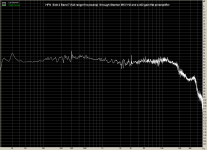
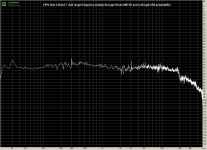
Stanton MKV H2 cartridge on Kenwood KD-3100 turntable, to Hagerman Bugle RIAA pre, to M-Audio Audiophile USB card. 24bit/96KHz recordings.
22d Celcius ambient temp (+/- 0.1).
FFTs (4096 samples) zoomed in the range 3KHz to 22KHz
Then I played Side 2 Band 7 (full freq sweep ) from HFN Test LP for ten consecutive times. Repetition interval 40 seconds.
Then, I played the same freq sweep track after 2h 45min.(again I had excercised the cartridge by playing for 20 minutes the same music vinyl LP).
Thanks for these George. It'll be a few days before I can have a proper look at them cos some beach bum issues pending 🙂I replayed that track 34h after the last play
The ambient temperature during that play was 23.3d Celcius.
here is the wav file (L channel 1st play, R channel play after 34 hours)
https://www.dropbox.com/s/ooga2pzt1no9270/L1st%20R34h%20later.wav?dl=0
A couple of clarifications please ..
- Is L channel always the original 1st play on all the tracks?
- What is the specifiedfrequency range of the HFN sweep track?
- Do they say how the track was produced originally?
There are important caveats using 'small' FFTs to look at a sweep signal like this. A sweep like this (through an RIAA preamp should show relatively flat response. If it doesn't, you are almost certainly just shuffling measuring & processing artifacts around.
I might have to actually do something serious with GNU to process this. It's already brought up an important point if we are to use Test Record Sweeps to determine EQ required. My 1980s DOS compiler can't do 2M FFTs 😡
I'll fire up my vintage B&K 2307 chart recorder to measure the response as God intended. Its getting harder to get the steam to run it. Don used a B&K 2305 😀
Last edited:
Long summary post
My apologies in advance for this long post, in which I summarise my thoughts on mechanical resonance as they have evolved while reading this thread.
Firstly, thank you Lucky for proposing a thought-provoking transmission line model that simulated results in keeping with the Happ/Shibata charts you posted earlier. Your approach is in the spirit of Paul Dirac, who was fond of putting forward mathematical analyses that got the experimenters scrambling. With the caveat that I would really like to find the paper containing those charts, I have some thoughts to offer.
Those charts show a first resonance around 20kHz and a second around 40kHz. That is more consistent with the cartridge end of the shank being partially constrained, rather than fully constrained as would be the case for a “proper” cantilever. A cantilever with one end fully constrained that showed its first resonance at 20kHz would show its second resonance around 125kHz, rather than 40kHz.
Happ’s Figure 5 model in Shure’s online technical seminar includes parameters Rw and Vw at the shank pivot that potentially “relax” the pure cantilever constraints. Finagling something similar using the Bernoulli-Euler equations for beam flexure, I get rough-as-guts estimates of wave numbers of the resonant modes at 1.0, 1.8, 3.2 and 4.8 so that, if we take the first mode as being at 20kHz, we get successive resonances at 36kHz, 64kHz and 96kHz – and 36kHz is a lot closer to the Happ/Shibata chart than 125kHz!
If that sort of approach is on the right track, then kgrlee’s “rubber bung” and billshurv’s elastomer grommet become a rather important component. Groh and Van den Hul think so too – and I am inclined to follow their lead, especially on the matter of the frequency dependence of grommet compliance and damping. Yes, there is the tie-wire at the cartridge end of the shank, though I want to treat it solely as a device for holding the pivot point in place relative to the cartridge body rather than an important part of the shank system (which is already complicated enough!).
So, having looked at the constraints at one end of the shank (whether modelled by a flexural mechanical system or by transmission-line analog) I turn to the other end, which is where I think that my view parts company with Lucky’s. The Shure comments on vinyl/tip compliance (post #856) and the vinyl ester data (post #858) lead me to believe that incorporating some vinyl/tip compliance is a useful boundary condition to apply at the stylus end of the shank. At one extreme, the constraint could be modelled with zero compliance (I think this is your view, Lucky, pls let me know if I have that wrong) or at some other value that is less than the compliance of the rest of the shank (as in the Shure example, where it appears to be modelled at 1/8th of the compliance of the cantilever assembly).
Where to from here for me? Well, I would LOVE to find the source of the Happ/Shibata charts to read what they were up to, theoretically and experimentally. Equally, I would appreciate anyone’s thoughts on transforming a cantilever with distributed compliance and mass into an analogous transmission line with distributed inductance and capacitance.
Anyone know if Audacity's resampling is correctly anti-aliased ?I might have to actually do something serious with GNU to process this. It's already brought up an important point if we are to use Test Record Sweeps to determine EQ required. My 1980s DOS compiler can't do 2M FFTs 😡
Newbie thoughts 😱
Can we deduce that in ideal situation there is minor/no degradation of vinyl modulations? (As for every action there is equal and opposite reaction so probably vinyl material is such that it displaces the stylus due to its compliance instead of bearing the brunt).
So if we deliberately increase tracking force use very low compliance cartridge and measure high frequency contents at the beginning of the vinyl at higher speed (45rpm) we may get some 'exaggerated' degradation measurements and by that the safe zones for tracking force/compliance/stylus point shape etc. AND as is being discussed other distortions measurements.
Regards.
A couple of clarifications please ..
- Is L channel always the original 1st play on all the tracks?
Yes Ricardo. It’s always the recording of the 1st play (copy and paste)
But keep in mind that, that 1st play wasn’t the virgin play of that track. It has been played again in the past, I can say less than 10 times, maybe 5.
And in all these recordings I uploaded, it is the L output of the cartridge that I have utilized.
Not a specification but this is what they report: "Full range frequency system check (20Hz -20KHz L+R)"- What is the specifiedfrequency range of the HFN sweep track?
There is no technical details on how this track or the whole disk was produced, not even what cm/s they consider as their 0dB. There is only this information:- Do they say how the track was produced originally?
"In 2002 Len Gregory aka the cartridge man decided to update the original release and returned to the Exchange studio for a new recording session."
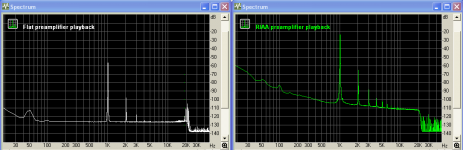
There are important caveats using 'small' FFTs to look at a sweep signal like this. A sweep like this (through an RIAA preamp should show relatively flat response. If it doesn't, you are almost certainly just shuffling measuring & processing artifacts around.
What is printed on the vinyl in this track is flat, no RIAA emphasis. See attachments from flat playback.
George
Attachments
Regarding Scott’s and Lucky’s comments on distortion measurement as more appropriate way to check for vinyl distress due to repeated playback, I’ll try it with single frequency tracks, although I expect the effects will be really minor compared to the distortion quantities already present on a single play.
I would love to see an FFT from a laser playback system of a single tone test track. This would show us how much distortion is attributed to disk cutting alone.
George
I would love to see an FFT from a laser playback system of a single tone test track. This would show us how much distortion is attributed to disk cutting alone.
George
Attachments
Thanks George.Not a specification but this is what they report: "Full range frequency system check (20Hz -20KHz L+R)"
What is printed on the vinyl in this track is flat, no RIAA emphasis. See attachments from flat playback
I'm suspicious that your 2 attached thumbnails are both roughly 'flat'. They should differ by the RIAA EQ.
What is the software doing the FFT? ARTA? What size?
I suppose what I'm saying is I don't think you can use a 4096 pt FFT to make sense of a sweep which is 1M8 long
We need to sort this out if we are to use these measurements to dream up a digital EQ ... or decide if "meaningful deformation can exist at all in the dynamic case at hand" Just the practice will do. Theory has to explain practice .. not the other way round 😎
Last edited:
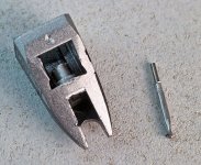
Whilst digesting Bondini's post I was left last night wondering how Ortofon do the damping on their MMs. They have a fancy 'wide range damping' setup on their MCs with a platinum washer and two rubber donuts. So did some googling.
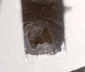
First pic shows one of the DJ stylus assemblies. Second shows a shot into the suspension of this. This nicely shows the asymmetric suspension that LD has mentioned and I want to use as the basis of frankencartridge. Behind that you can see a second rubber ring that the moving iron slides into, which I assume is for the damping. This does mean that, for those who have access to a technical rubber lab you could adjust that to suit...(note not me)
First pic shows one of the DJ stylus assemblies. Second shows a shot into the suspension of this. This nicely shows the asymmetric suspension that LD has mentioned and I want to use as the basis of frankencartridge. Behind that you can see a second rubber ring that the moving iron slides into, which I assume is for the damping. This does mean that, for those who have access to a technical rubber lab you could adjust that to suit...(note not me)
Attachments
On cartridges without a tie wire ... certainly the ADC XLM/VLM/ZLM variants and apparently the Ortofon MMs ... the hole size in da bung is similar for many of their expensive cantilevers as for their cheapo DF versions. (Please check this. Don't take my word for it before taking your $$$ cartridge apart. )Whilst digesting Bondini's post I was left last night wondering how Ortofon do the damping on their MMs. They have a fancy 'wide range damping' setup on their MCs with a platinum washer and two rubber donuts. So did some googling.
First pic shows one of the DJ stylus assemblies. Second shows a shot into the suspension of this. This nicely shows the asymmetric suspension that LD has mentioned and I want to use as the basis of frankencartridge. Behind that you can see a second rubber ring that the moving iron slides into, which I assume is for the damping. This does mean that, for those who have access to a technical rubber lab you could adjust that to suit...(note not me)
This means us mere mortals can easily do a cantilever swap without damage. If you put a state of the art, low tip mass cantilever, into a stiffer bung (below 20cu), you will find the 'first resonance' moves even higher in frequency (compared to the original low tip mass cartridge) with corresponding improvements in HF trackability .. which was my main concern.
The cartridge will be better suited to other than ultra low mass arms. LF trackability will be reduced but this is always ample in modern cartridges. The lower compliance allows a higher tracking weight too.
BTW, this isn't theoretical pontificating but experimental evidence. The scientific method requires theory to fit evidence .. not the other way round.
Last edited:
well good to know that there is prior for the intended experiments.
But the bit I am not sure about is that the shure setup is 2 bungs. so In theory you can mess with compliance and Damping. Where does the trade off lie, and is there anything that can be measured on the virgin cartridge to work out what effect it might have.
The ortofon range goes from compliance of 6 up to about 25 so in theory a lot of permutations!
If you mean the V15-4 in Fig 10 of Design Considerations of the Vl5 Type IV Phonograph Cartridge - L. R. Happ fromBut the bit I am not sure about is that the shure setup is 2 bungs. so In theory you can mess with compliance and Damping.
High Fidelity Phonograph Cartridge - Technical Seminar | Shure Technical FAQ ..
there isn't actually a 2nd bung.
The 'damping' is actually a lump of rubbery goo stuck on the end of the magnet. The stylised representation is Fig 10 in
http://shure.custhelp.com/ci/fattach/get/29245/
In da old days, it was difficult to get 'rubber' made to spec in small quantities. I remember a seminar at a London AES, 1979 IIRC, where all the big UK speaker R&D big wigs answered questions from the floor.
Ken Russell, Rank Wharfedale, said "if all the companies represented here agreed on a single formulation for speaker surrounds, half a day's production from ICI would see us all for the next 5 yrs"
??, MD of Goldring, from the audience then stood up & said, "for all the cartridge makers worldwide, it would be about a pound of goo for 10 yrs." 😱
Material for surrounds was always dictated by what the tyre companies were using .. both 'natural rubbers' as well as the synthetics.
Today, the advent of boutique 'silicon rubbers' make small quantities for cartridges much easier .. though not in the quantities for speaker surrounds 🙁
My experience is that static compliance is always greater than the number in the 'spec' .. measured with travelling microscope & adjusting tracking weight.The ortofon range goes from compliance of 6 up to about 25 so in theory a lot of permutations!
Fig 8 in the above Happ paper confirms this trend .. which may be why SHURE don't like quoting compliance
1. I have been silently lurking and following this thread with much interest. As explanation for this long post, in a prior life I was an aerospace test engineer flight testing navigational systems. But on the side, and purely as a hobby, I spent a good portion of my free time -- and my employer’s computer resources -- devising a FORTRAN model for phonograph playback. My approach was originally based on the work published by Shure, then elaborated by more detailed electrical analogs of stylus dynamics, vinyl deformation, tone arm interaction, electrical filter response, eddy current/hysteresis losses, blah, blah, blah. None of this was terribly original, but was based on published literature. Lots of it.
Most of my effort was directed on modeling the Shure V15-III because: (1) There was considerable information and test data published on this pickup, and (2) Vested interest: I was using one at the time. In the end, the model seemed to agree well with available data which instilled some confidence in its validity.
Two major takeaways:
(1) The deeper one digs into it, the more complex phonograph playback becomes. (This thread attests to that!) Pun: I mean “complex” in the mathematical sense. There are many interactions to consider, and many resonances to damp. Thomas Edison remarked that the phonograph was his only invention that worked at first try. After studying pickups, one wonders that the thing works at all.
(2) It is not difficult to design a pickup having reasonably flat frequency response, or a pickup exhibiting good tracking ability. But it is extremely challenging to design a pickup having both flat response AND high trackability over the entire frequency range of interest. As a corollary, it’s not surprising that so many phonograph pickups sound good playing music. The pickups are forgiving. However, the records are not. High tracking ability saves records. Good trackability beyond 20 kHz insures low record wear when tip tracing distortion creates harmonics of music content.
A few comments pertinent to this thread. Starting at the diamond tip:
2. Lucky’s analogy of the stylus tip doing a high-speed skate on top the groove walls is an interesting concept. But what is “high” speed? Agreed there is vinyl indentation at rest: at what linear groove velocity does the indentation become negligible? Perhaps it’s more like surfing than skating? Surfboards leave a wake.
Whether static or in motion, interaction between the diamond tip and vinyl groove walls is dependent on tip geometry and vertical tracking force (VTF). With modern pickups groove wall indentation is hopefully elastic, and record wear minimal. But that the vinyl presents both compliance and damping to the driven tip shouldn’t be ignored. And not all “vinyl” is the same. Polystyrene records ring audibly when tapped, PVC records less so.
In earlier pickups with high tip mass, high VTF, and stiff cantilever bearings, the stylus/vinyl resonance may well have been the dominant limitation in frequency response.
Effective vinyl impedance, along with friction, is dependent on VTF and tip geometry. Changing from a spherical tip geometry to an elliptical or fine-line geometry changes more than stylus tracing geometry – indentation changes and this changes the compliance and damping as felt by the diamond tip. Thus frequency response and trackability will change. Changing this one thing changes everything downstream.
3. I believe that Lucky is correct in that modern pickup cantilevers show transmission line behavior, due to cantilever bending. I modeled it as a distributed parameter electrical transmission line with mismatched impedance terminations at both stylus tip and pivot bearing ends.
Again, in older times when extended frequency response was a driving goal, cantilevers were stiff beams to minimize bending loss at high frequencies. A simpler model sufficed but trackability (and record wear) suffered.
4. The tiny rubber donut comprising the cantilever bearing is a study upon itself. bondini is absolutely correct in recognizing its importance. It’s possibly the most interesting part of a phonograph pickup.
Shure models the bearing’s mechanical impedance as a compliance C and damping resistance R. As Happ and others explain, the mechanical impedance of this bearing plays important roles in tone arm resonance control and in pickup performance in the audio range and above. Happ’s paper alludes to these factors having a frequency dependence which was determined empirically, and references a text by Snowden (J.C. Snowden, “Vibration and Shock in Damped Mechanical Systems”). I used Snowden’s graphs of frequency dependence of dynamic shear modulus and damping factor to quantify C and R in my model.
A butyl rubber compound is seemingly commonly used in this application, the exact formulation being proprietary. Snowden’s data shows butyl’s mechanical impedance to be relatively constant up to 100 Hz, with compliance C changing slightly at higher frequencies. However, butyl’s damping R increases by an order of magnitude as frequency rises.
Also of importance, Snowden shows these values are a strong function of temperature, butyl’s R changing by an order of magnitude (at 10,000 Hz) over a temperature range 5 to 35 deg C. This implies that phonograph response, particularly tracking ability, is highly temperature dependent. (Note this is the temperature of the stylus bearing, which from groove friction would be somewhat higher than ambient room temperature.)
Choice of elastomer compound for the stylus bearing is a compromise. One wants high damping at subsonic frequencies for tone arm resonance control, low damping at mid-high frequencies so not to inhibit tracking, and moderately-high damping at the highest frequencies to control various resonances. The bearing must remain effective over a range of temperatures, and remain stable over a reasonable time period.
As billshury mentioned, some Ortofon pickups have a compound bearing using multiple elastomers having different frequency/temperature properties. A few of Shure’s had a second elastomeric mass on the bearing, intended as a tuned vibration absorber as described by Happ.
Some pickups use a “tie-wire” to stabilize the cantilever and bearing. Depending on geometry, this wire can add a pure spring force to decrease stylus compliance at subsonic frequencies independent of elastomer compliance. The wire also serves to partially support the static VTF so that the elastomer isn’t overly compressed.
Some pickups employ an external damping mechanism (e.g., a brush, viscous damped or not) to help control tone arm resonance. This alleviates the elastomer bearing of subsonic damping duty.
5. Apparently unmentioned in the literature, is eddy current damping of stylus motion. A moving magnet pickup having user-replaceable stylus typically has the magnet and bearing encased with a nonmagnetic metal tube which inserts within the pickup’s coil structure. I believe that eddy currents generated in the metal tube provide some damping to control the magnet’s resonant motion.
6. Apologies for hijacking this thread at such length. I shall now return to lurking, with hopes the discussions will continue. There’s much to be learned about these confounded talking machines.
Charlie
- Home
- Source & Line
- Analogue Source
- mechanical resonance in MMs