Hello guys,
I'm bringing up this old thread as I' m currently simulating a TMC design. I think I am lost in plotting the results of OLG using Middlebrook Tian probe. I get almost 83dB and not so sure if this is way too high to a conventional Blameless design.
Can anyone give me an idea how and where to properly place the Tian probe? Any pointers and reference links is much appreciated.
Sa muli,
Albert
I think I am lost...
Hi Albert
Your description is confused but the actual probe placement is OK.
There is no "Middlebrook Tian", there is a Tian Probe and this is what you have.
The term "Middlebrook Probe" is open to confusion because he described several old techniques in 1975 as well as invented a new one, and then an improved version after 2000. The later version is called Middlebrook GFT.
What Tian shows is not Open Loop Gain but Loop Gain, I prefer to use the term Return Ratio because it creates less confusion and was the term used by Bode, who worked all this stuff out first.
Your 79 dB is not unbelievable in a Blameless with current mirror, an EF assisted VAS.
Best wishes
David
Last edited:
Typically we can expect a total open loop gain of a Blameless topology of 110 to 120dB at low frequencies.
If one subtracts 33.6dB from that for the amp gain then one is left with 76.4dB to 86.4db for the loop gain (return ratio) at those lower frequencies.
R17 is too high.
It allows a Multiplier ratio up to 3.5times Vbe
Try 2k for R16 and 510 for R17 allowing a Multiplier ratio upto 4.9times Vbe
Check whether R7 is the correct value for the VAS current you want to pass.
Last edited:
Hi Albert
Your description is confused but the actual probe placement is OK.
There is no "Middlebrook Tian", there is a Tian Probe and this is what you have.
The term "Middlebrook Probe" is open to confusion because he described several old techniques in 1975 as well as invented a new one, and then an improved version after 2000. The later version is called Middlebrook GFT.
What Tian shows is not Open Loop Gain but Loop Gain, I prefer to use the term Return Ratio because it creates less confusion and was the term used by Bode, who worked all this stuff out first.
Your 79 dB is not unbelievable in a Blameless with current mirror, an EF assisted VAS.
Best wishes
David
Hello Maestro Dave,
My apologies for the confusion, I was under the impression that the improved work of Dr. Middlebrook being shared at LTSpice site was called Middlebrook Tian. [the inventors I think]. Thank you for clarifying this matter.
The amp posted above had a 33dB closed loop gain, Is it possible to come up with an estimated figure for open loop gain if I had a loop gain of 79dB?
Regards,
Albert
Hi Albert
Your description is confused but the actual probe placement is OK....
In such a case, what about C4? Do you think it's permitted to be in the loop?
Typically we can expect a total open loop gain of a Blameless topology of 110 to 120dB at low frequencies.
If one subtracts 33.6dB from that for the amp gain then one is left with 76.4dB to 86.4db for the loop gain (return ratio) at those lower frequencies.
R17 is too high.
It allows a Multiplier ratio up to 3.5times Vbe
Try 2k for R16 and 510 for R17 allowing a Multiplier ratio upto 4.9times Vbe
Check whether R7 is the correct value for the VAS current you want to pass.
Hi AndrewT,
R17 is originally 2k however I could not balance the currents at outputs ballast resistor. I had to adjust it to 2k7. I will try your suggestions, right now it is still showing a few glitches? At positive swing at clipping level.
Albert
[I could not balance the currents at outputs ballast resistor
what is this referring to?
what is this referring to?I could not balance the currents at outputs ballast resistor
R23,24,25,31 [output] in the schematic. Anyway I tried your suggestion of lowering R16, & R17 It seemed to work nicely. 😉
Hi, Leach wrote in his past articles that to avoid TIM,
open loop gains are not to be too high, not more than 60db...
so how do you do a long hand computation of OLG from the circuit?
and how do you do an actual OLG testing and measurement in an actual circuit?
open loop gains are not to be too high, not more than 60db...
so how do you do a long hand computation of OLG from the circuit?
and how do you do an actual OLG testing and measurement in an actual circuit?
...I was under the impression that the improved work of Dr. Middlebrook being shared at LTSpice site was called Middlebrook Tian. [the inventors I think]...
The "Tian" probe was the work of Michael Tian, V. Visvanathan, Jeffrey Hantgan, and Kenneth Kundert - shortened for obvious reasons.
The actual LTspice implementation is due to Frank Wiedmann, who deserves more credit for his excellent work
The amp posted above had a 33dB closed loop gain, Is it possible to come up with an estimated figure for open loop gain if I had a loop gain of 79dB
Yes, as Andrew's post implies, the Open Loop Gain is just the Loop Gain plus the Closed loop Gain.
Are there other loops that need...
In such a case, what about C4? Do you think it's permitted to be in the loop?
I did notice C4 but I am fairly confident it won't make a major difference to the results for this probe placement.
That's why I said it's "OK" rather than perfect.
I still haven't completely clarified how to tie the theory and my simulation observations.
Once I work it out I will definitely write it up.
Best wishes
David
Hi, Leach wrote in his past articles that to avoid TIM,
open loop gains are not to be too high, not more than 60db...
so how do you do a long hand computation of OLG from the circuit?
and how do you do an actual OLG testing and measurement in an actual circuit?
maybe you didn't read all of it - Leach joined Jung in repudiating their 1st opinions on Otala's "flat loop gain" over audio prescription
both recognized, wrote later, that low "TIM/SID/PIM" could be obtained in high loop gain amps with high, sloping gain over audio
a high loop gain capable amp can easily use that gain with 2-pole compensation to reduce all IMD products, regardless of phase
http://www.diyaudio.com/forums/loun...ch-preamplifier-part-ii-9215.html#post5066347
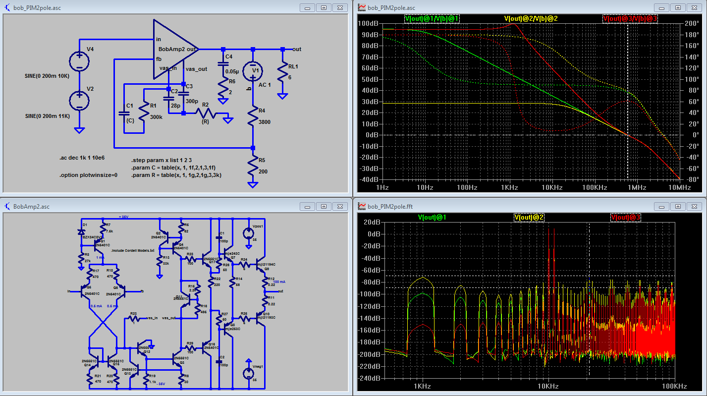
amp from Bob's book - 3 compensations:
green trace - nominal dominant pole
yellow trace - added 300k R, R||Cdom to flatten gain, get "wide open loop gain" (couldn't load the beta enhanced VAS out heavily enough with shunt R to gnd)
red trace - 2-pole
Last edited:
maybe you didn't read all of it
i read the debate between Leach and Cordell at the Audio magazine many many years ago..i have made super leach amps in the 80's and people who heard this amp liked what they heard...
i also remember that with tubes, open loop gains were not that high.....
some did not even have global negative feedback networks...
but still some had lots of local negative feedback...
yes, maybe i need to change my thinking.....
and like they say, the acid test of the pudding is in the eating...
so how do you do a long hand computation of OLG from the circuit?
and how do you do an actual OLG testing and measurement in an actual circuit?
anyone?
and how do you do an actual OLG testing and measurement in an actual circuit?
anyone?
The "Tian" probe was the work of Michael Tian, V. Visvanathan, Jeffrey Hantgan, and Kenneth Kundert - shortened for obvious reasons.
The actual LTspice implementation is due to Frank Wiedmann, who deserves more credit for his excellent work
Yes, as Andrew's post implies, the Open Loop Gain is just the Loop Gain plus the Closed loop Gain.
Best wishes
David
This is quite helpful, it cleared some misunderstandings in my learnings in audio amplifier.
Thank you!
Albert
...how do you do hand computation...
Read Bob Cordell's book, all described there.
and how do you do... measurement in an actual circuit?
This can be quite difficult in a real circuit with lots of gain.
And not that useful anyway if the circuit is intended to run closed loop.
Bob's book is worth a look for this too.
Best wishes
David
- Status
- Not open for further replies.
- Home
- Amplifiers
- Solid State
- How to simulate an OLG of the TMC amp