Vishalk, the last 2 capacitors can be 1-2,2uF MKP, non inductive type. And don't forget the bleeders.
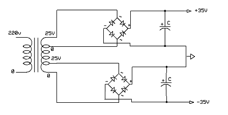
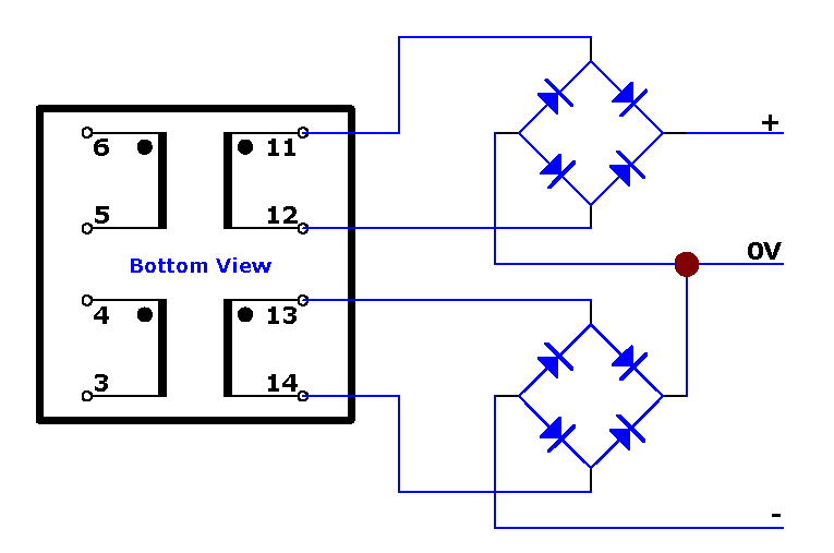
Also, the schematic you drew is one possibility. There is another one, much better in terms of noise, that use 2 rectifying bridges, one for each secondary winding of the trafo. The great advantage is that you don't return ground into the trafo.
Gentlevoice - thank you. When I wrote "transients" I was referring to "attack". Obviously there are no square signals in music.
LE - The LL2733 is dedicated for filament supply filtering. That doesn't mean it cannot be used as a filter for symetric + and - rails (same as dual coils are used in EMI filters). The advantage of this use is that saturation current increase [a lot].
Last edited:
I don't think it is out of context. The phrase bass transient comes up quite a lot, and unless it means something other than a quick event when used like this then it makes no sense to me
Pano, for what I know there are transients on bass too.
I've read years ago part of that french documentation, I'll read it all. Btw - thanks Sergiu for the link to that Index.
Using coils is a big step forward to a great PS, despite the relatively big cost involved.
A soft start module is cheap and usefull when trafo > 5-600VA. It also permit a low charging of capacitors.
Of course, a high quality relay is mandatory 🙂
I was wrong yesterday recommending lower L with very low Re - it's good for an AB class amp.
In this case of an A class, it is not so important to keep Re very low as long as the consumption is constant, so the supply voltage will not variate.
Hi Shambala,
You're welcomme.
Cheers

1uF to 2.2uF (i used 2.2uF MKT) as Shambala sayed, and a very nice adenum wich i have readed from L'audiophille magazine, is the adenum of an 100uF to 220uF/35~40V depending of the voltage from the cap bank, as close as possible to the wires that goes to the amp, on the cap bank pcb (it was measured and tested by Jean Hiraga himself and proven to be even better if coupled with this 2.2uF, when measured with scope). I have readed this info from another article but havent tested yet soundwise..
Cheers
Those 100-220uF should be of very good quality, Nichicon or Elna top series capacitors, with high Rf. And it can very well be at 50V.
Don't forget to ad 0,1uF mkp on the amp pcb. Or rails snubbers if you want to cross the audiophile line 🙂
Btw, I saw nobody use snubber for the rectifiers. Haven't you tried ?
With choke filter effect is dimm, but for CRC filters should be significantly.
Don't forget to ad 0,1uF mkp on the amp pcb. Or rails snubbers if you want to cross the audiophile line 🙂
Btw, I saw nobody use snubber for the rectifiers. Haven't you tried ?
With choke filter effect is dimm, but for CRC filters should be significantly.
Last edited:
Well if i'm going to build this Hiraga i might aswell do it properly. I'll buy quality components, it's nice for the help and recommendations from you guys.
https://en.wikipedia.org/wiki/Snubber
Interesting, Snubber circuits. My thoughts were with a soft start, the chokes, making an effort to isolate any forms of magnetic interference etc i wouldn't require one?
If it's a useable option then i will consider it, i want to keep it practical and simple. Give me more information on it.
Those 100-220uF should be of very good quality, Nichicon or Elna top series capacitors, with high Rf. And it can very well be at 50V.
Don't forget to ad 0,1uF mkp on the amp pcb. Or rails snubbers if you want to cross the audiophile line 🙂
Btw, I saw nobody use snubber for the rectifiers. Haven't you tried ?
With choke filter effect is dimm, but for CRC filters should be significantly.
Vishalk, the last 2 capacitors can be 1-2,2uF MKP, non inductive type. And don't forget the bleeders.
Bleeder resistors? Didn't think it was needed?
Also, the schematic you drew is one possibility. There is another one, much better in terms of noise, that use 2 rectifying bridges, one for each secondary winding of the trafo. The great advantage is that you don't return ground into the trafo.
I was considering this, but is it really necessary? Plus it's more work and parts. Surely with rectifiers being more modern and better, the use if chokes and good capacitors it would be more then ok? 😱 Putting ideas in my head, now i'm wondering if i should do a dual bridge rectifier circuit.
An externally hosted image should be here but it was not working when we last tested it.
An externally hosted image should be here but it was not working when we last tested it.
Gentlevoice - thank you. When I wrote "transients" I was referring to "attack". Obviously there are no square signals in music.
LE - The LL2733 is dedicated for filament supply filtering. That doesn't mean it cannot be used as a filter for symetric + and - rails (same as dual coils are used in EMI filters). The advantage of this use is that saturation current increase [a lot].
Need to be able to run bias @ 1.5-1.65A want the power supply to be more than sufficient and clean to power those amplifiers.
Last edited:
Hello,
If you dont mind reading. Read this one i have posted this link in other threads too.
RR#002 - DC Filament Supply Test
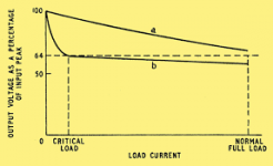
If you dont like reading just take a look at this drawing. It shows a good reason to use a bleeder. Especially if you are using caps close to their maximimum working voltage.
I know you if you have 25 volts dc on the first cap you will have to '' bleed '' 25volt divided by 0,1H =250 mA to make it work as a true choke input. If you put the coils in series and create a 400mH that current just needs to be 62,5 mA. It could well be possible that the 3,4 ohm from this 400mH. You will have to try.
If you dont agree i would certainly put a smaller resistor to at least have some current to stop the voltage at the first cap going up like there is no choke at all.
greetings, Eduard
If you dont mind reading. Read this one i have posted this link in other threads too.
RR#002 - DC Filament Supply Test
If you dont like reading just take a look at this drawing. It shows a good reason to use a bleeder. Especially if you are using caps close to their maximimum working voltage.
I know you if you have 25 volts dc on the first cap you will have to '' bleed '' 25volt divided by 0,1H =250 mA to make it work as a true choke input. If you put the coils in series and create a 400mH that current just needs to be 62,5 mA. It could well be possible that the 3,4 ohm from this 400mH. You will have to try.
If you dont agree i would certainly put a smaller resistor to at least have some current to stop the voltage at the first cap going up like there is no choke at all.
greetings, Eduard
Attachments
Using two bridges is the best solution if you want the best result. It is important not to return into trafo all noise collected by ground.
In RCLC Circuit says "C1 should be equal or smaller then C2". Well, in the PS for a Hiraga 30W it should be much smaller than C2, 4 to 10 times smaller. Both, not to saturate the core of the trafo and not to "choppe" to deep the dc, as showed in the DC Filament Supply Test.
In RCLC Circuit says "C1 should be equal or smaller then C2". Well, in the PS for a Hiraga 30W it should be much smaller than C2, 4 to 10 times smaller. Both, not to saturate the core of the trafo and not to "choppe" to deep the dc, as showed in the DC Filament Supply Test.
Last edited:
I forget to say that in a practical aplication of RLC or RCLC from (Lundahl Plate chokes, Lundhal Anodendrossel), R1 is out of the question, the soft start (before the trafo) do the job of limiting charge current for the trafo, the C and L.
When I wrote "transients" I was referring to "attack".
Do you mean "attack" as in something happening quickly, as in the envelope of sound ie (ADSR) that is Attack Decay Sustain Release?
I must learn some more words before answering, it seams that I already missed twice the correct expression.
Sorry :$
I will rephrase in a few hours.
Sorry :$
I will rephrase in a few hours.
Last edited:
Ha ha, it's ok, what I query like a couple of others is the idea of bass transients because it implies high frequency
Hello,
I guess all the information to get things started has been given ( did also write a personal message with some more info to the original poster.
A brief survey according to my point of view lol
Dont use a toriodal transformer.
Try to find R core like this one
Shilchar Technologies Ltd.
The 600VA core will be big enough especially if you are going for a choke input!
Put the rectifier close to the transformer and put the pair of ll2733 close to the rectifier. The first cap close to the choke.
You could make a LCRC where R can be just a very small one like 0.1 ohm and put the last caps close to the circuit.
Probably can put the bleeders on the first caps.
First test the output voltage of the power supply by creating a similar load as the circuit with a BIG resistor across the terminal of the final caps so one between plus and centre tap and one between - and centre tap. 25volt/15 ohm will give 1,66 A
All has been said and done. I mean the proof of the pudding is in the eating.
greetings, Eduard
@ scottjoplin - I was unable to find the certain english expression for what I meant so I will explained it in many words 😱
I was referring to the very first moment of ADSR (in accordance with Wiki def.), the very fast, very abrupt increase of the signal for a very short time (dt) - when the big drum is hit, for instance.
It is a moment when a lot of energy is demanded from the capacitors of the PS, and where low-esr is important. And it is in the low frequencies (at least for the big drum), even if sometimes the theoretical analysis approach it as square signal (which is not).
Eduard, I think the bleeder would be better placed on the biggest caps pack.
Last edited:
Yes, understood. Stored energy instantly on hand for that drum beat, I couldn't agree more. I think what happens quite often, and please Pano and Gentlevoice correct me if I misinterpret what you meant, and what I also thought, is when potentially ambiguous words are used to describe what is meant, in this case bass transient. Purely a misunderstanding I believe.
After thinking a little more and for the sake of truth, I must say to Pano and everybody that in this case, my affirmation might be inaccurate, or at least irrelevant.
What I said is perfectly true for class AB amps, where consumption is varying by the power output.
In case of an A class amp, where the current demanded from the PS is mainly constant - there are not sudden current peaks, it may be less important if the capacitors are low-esr or not.
However, due to the very big value of C, want it or not, esr is very low anyway.
Last edited:
Wouldn't two bridges just create more noise? This also means i need to have a transformer with 2 completely separated windings = 4 wires.
To use 2 bridges on one 3 wires 12-0-12 transformer is not possible?
My thoughts is this is classic amplifier, and some 30 years ago till now the power supply design hasn't really changed. Over those many years components have improved considerably. Take for example the rectifiers, today's technology to say 20 years ago you cant really compare.
Would you really notice the difference using two bridges? Still researching on this:
http://www.diyaudio.com/forums/pass-labs/93712-dual-bridge-rectifiers-psu-why.html
Using two bridges is the best solution if you want the best result. It is important not to return into trafo all noise collected by ground.
In RCLC Circuit says "C1 should be equal or smaller then C2". Well, in the PS for a Hiraga 30W it should be much smaller than C2, 4 to 10 times smaller. Both, not to saturate the core of the trafo and not to "choppe" to deep the dc, as showed in the DC Filament Supply Test.
- Home
- Amplifiers
- Solid State
- Jean Hiraga Super Class A 30w Build