This is a universal differential or single ended output to compliment the phono front end. Bob Cordell used IC op-amps to provide gain and additional RIAA time constants here only gain is needed. It has been suggested that the impedances of the original front end could be scaled to get 40db of gain directly. Since this involves a lot of recomputing and checking I leave ths as a later experiment.
For the first circuit the options are:
1) Simply use one of the outputs with choice of phase. I recommend gain of 5 (14dB) to bring the gain to 40dB. Of course you could use just one 1512 for max economy.
2) As shown this is fully differential in and out so the gain is now 46dB total. This also has a 3db noise advantage, the 1512's are effectively in parallel for noise since adding uncorrelated noise does not care about phase.
3) Not shown but it is possible to add a simple servo from each in-amp output to the reference pin (5), a simple op-amp integrator will do.
The second circuit sums the two in-amps with no extra components for a dedicated single ended output, giving again 46dB of gain and 3dB less noise. All these options could easily be a few jumpers or dip switch. We published this circuit as a design idea in EDN over 30yr. ago and it actually won the $150 best of prize!
Attachments

I was looking at that EDN article this morning. When you open the THAT catalogue there are a range of options which can confuse. I notice Wayne Kirkwood uses the THAT1240 in the same position, but he is after max CMRR.
Looking at it the 1512 is no slouch on its own for noise (1.3nV/rtHz at 60dB gain). Arghh another device I 'need' a stash of.
Looking at it the 1512 is no slouch on its own for noise (1.3nV/rtHz at 60dB gain). Arghh another device I 'need' a stash of.
Two THAT1512 and two resistors? And then just a PSU that's VCC+ VEE- ?
So I can just have an output switch to select which phase I want, and with single ended there's just a common circuit ground? And I can dip switch resistors for gain?
This is insanely easy. Oh wait, no RIAA network...
So I can just have an output switch to select which phase I want, and with single ended there's just a common circuit ground? And I can dip switch resistors for gain?
This is insanely easy. Oh wait, no RIAA network...
Last edited:
Yes, this works with any of the IC instrumentation amplifiers but the 1512 is the quietest at lower gains and is only around $5-6 at Mouser in single quantities. This is what I suggest to put after the discrete RIAA front end that I posted to make a complete pre-amp.
George was supposed to put all the other posts here before this one.🙄
George was supposed to put all the other posts here before this one.🙄
Where is this RIAA front end? You have an interesting way of making puzzles, Scott.
I bet there's someone that could make a GB PCB. If I'm not mistake this should be one of the cheapest, and hopefully best, phono preamps on the forum. That is if you're like me and when a device has a lot of parts you buy the good stuff.
I bet there's someone that could make a GB PCB. If I'm not mistake this should be one of the cheapest, and hopefully best, phono preamps on the forum. That is if you're like me and when a device has a lot of parts you buy the good stuff.
George needs to move the stuff from the Blowtorch thread to here, I can't do that only a mod can. Everything will be here eventually hopefully in the morning Greek time. Everything fits on a 1/2 Euro sized board for each channel, hopefully the BOM can be <$100 for two channels with everything unless you want crazy type components.
Exactly what I was thinking. The only expense is caps for an RIAA; unless it needs input/DC blocking caps. Maybe you should steal and fix up an active RIAA to diminish costs sub $75 or $50. At that point you could be sub $100 even with naked vishays if there's only two to four series resistors.
IIRC THAT chips block DC so there's no series cap needed?
IIRC THAT chips block DC so there's no series cap needed?
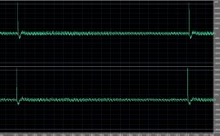
Yes the front end is in Bill's link. Open-loop passive RIAA and as some wondered here is a comparison between this and a commercial pre-amp on a full skipping LP recorded at only 4dB headroom on loud passages. Unfortunately it's my almost unplayed copy of "The Final Cut" . No overload issues.
Attachments
So are you feeding the THAT's with J4-7, or no, in this case?
I like the use of the nf caps. That keeps the expense down a lot.
The skip looks different but I couldn't "choose" one based on that, very comparable.
I like the use of the nf caps. That keeps the expense down a lot.
The skip looks different but I couldn't "choose" one based on that, very comparable.
So are you feeding the THAT's with J4-7, or no, in this case?
I like the use of the nf caps. That keeps the expense down a lot.
The skip looks different but I couldn't "choose" one based on that, very comparable.
Yes it becomes the output with all the CMRR benefits but with some gain to bring it to standard levels.
Very pleased to see this as a separate thread as it deserves.
As Scott has mentioned I am working on a version with 50~60dB gain at 1kHz.
It uses mostly 2SK372/369 as N-JFET instead.
Some question marks open about differential DC drift and noise of the RIAA network.
Shall report back when working successfully, but it will take quite some months.
First we have to get 500+2SK372's matched (curve traced).
Patrick
Scott, it's just a guess since there's no data on it but I'm guessing the THAT1512 is more accurate with current than most output devices. The internal diagram points that way from what I can tell, but obviously is somewhat vague. Maybe you can comment since you're the IC wizard. I just know I'll take better current performance over a little slew rate that'd help recovery a touch more. And you can't complain about the noise figures like you're saying with CMRR.
Very pleased to see this as a separate thread as it deserves.
As Scott has mentioned I am working on a version with 50~60dB gain at 1kHz.
It uses mostly 2SK372/369 as N-JFET instead.
Some question marks open about differential DC drift and noise of the RIAA network.
Shall report back when working successfully, but it will take quite some months.
First we have to get 500+2SK372's matched (curve traced).
Patrick
I was kind of excited by Scott's FET use, myself.
If you wish to have more gain, you need higher transconductance at the input.
No simple way round.
2SK372 also has the lowest noise.
Hence the choice.
http://www.diyaudio.com/forums/pass-labs/175040-more-fet-noise-measurements-euvl.html
Patrick
No simple way round.
2SK372 also has the lowest noise.
Hence the choice.
http://www.diyaudio.com/forums/pass-labs/175040-more-fet-noise-measurements-euvl.html
Patrick
Are they the most linear choice that you've been eye-ballin?
I trust EUVL to be thorough, if he expends the effort to follow through on a variant I agree to check it and make comments. My FET choice was for 3-5mV carts and from the plot a full groove skip or needle drop does not overload the input.
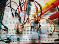
As a caveat this is a high impedance circuit the internal wiring can easily pick up vibrations, so fly wiring of inputs and outputs should be done with care and shielded and/or tacked in place with RTV. I have seen this also done to capacitors in other pre-amps.
Noise
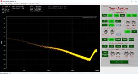
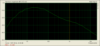
First test was bare inputs so the source impedance was the 47.2K termination (27.5nV) to check for hum/EMI, etc. The plot (@192K) conforms almost perfectly to the RIAA characteristic well beyond 20k. The noise peak beyond is the noise shaping of the converter (it's there all the time). No 1/f problems evident.
To step through computing the noise floor on an FFT one more time:
1) Bin width - 2.92Hz sqrt = 1.71
2) Hann window 1.7dB = 1.21
3) Noise 27.5nV/rt-Hz (1nV = -180dBV) x 1.71 x 1.21 = 56.9nV rms per bin
4) Gain @1k = 40dB
5) Noise at output = 5690nV per bin = -105dBV (pretty close)
Attachments
Last edited:
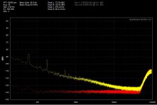
Noise with 50 Ohm terminators
Noise at 1K drops 15-16dB at 1kHz which is 4-5nV as expected. A little 1/f at 10Hz shows up and at 20kHz you would need extra gain to remove the noise floor of the QA400, but eyeballing it there are no issues.
The terminators are just RCA's with 50 Ohm resistors the slight 60/120/180 Hz incursion could be just that they make tiny antennas. I would need to borrow some sealed real terminators. In any case all this is swamped by any realistic surface noise.
I need to rewire my TT to do noise with cartridge load in situ.
Attachments
Last edited:
This is a universal differential or single ended output to compliment the phono front end. Bob Cordell used IC op-amps to provide gain and additional RIAA time constants here only gain is needed. It has been suggested that the impedances of the original front end could be scaled to get 40db of gain directly. Since this involves a lot of recomputing and checking I leave ths as a later experiment.
For the first circuit the options are:
1) Simply use one of the outputs with choice of phase. I recommend gain of 5 (14dB) to bring the gain to 40dB. Of course you could use just one 1512 for max economy.
2) As shown this is fully differential in and out so the gain is now 46dB total. This also has a 3db noise advantage, the 1512's are effectively in parallel for noise since adding uncorrelated noise does not care about phase.
3) Not shown but it is possible to add a simple servo from each in-amp output to the reference pin (5), a simple op-amp integrator will do.
The second circuit sums the two in-amps with no extra components for a dedicated single ended output, giving again 46dB of gain and 3dB less noise. All these options could easily be a few jumpers or dip switch. We published this circuit as a design idea in EDN over 30yr. ago and it actually won the $150 best of prize!
Hello Scott
Nice to see your new MM discrete JFET phono. A much to the point design.
Regarding your instrumentation approach side note quoted above it was also nice to see, as it so happened I was breadboarding something for DIF input very high gain LMC use lately and I had decided to check if INA structure could help me minimize such a build's complexity.
I initially composed an INA with OPA2134 and OPA134. I saw that the JFET input type accepts small enough coupling with acceptable LF noise so I can have a basic rumble filter and also avoid the input stage's differential DC drift that would lead to high level INA output offset.
I then ordered Texas INA217 (DIP8) but on experimenting I saw it needs lower source impedance (higher value coupling) for good LF noise. That fact creates a set of problems, like no rumble filter ability, lower quality electrolytic coupling caps, more input offset danger.
AD8429 could be bit nicer I thought, cheaper also, but its not breadboard friendly because SMD, still curious for testing it later on some PCB.
My question to you is, could it be you had been involved in its design and you know if the AD8429 is doing practically better on higher source impedance for LF noise than the Texas?
If not so, I could stick to composite INA made out of choice JFET input types or make JFET input discrete op-amps in their places.
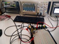
For the headamp input stage I tested with a ZTX851s LTP that gave me 50dB gain before I put the time constants networks across their collectors. 30dB after I did. Still potent enough to dominate the rest of circuitry noise wise. I also got good enough THD due to the low input levels. Input offset nulls well enough with a 220R trimmer between the 2K2 collector loads as I could not find any exact matches between 20 ZTX pcs and I would expect it getting worse with paralleled BJTs and higher bias, but I can alternatively test with few paralleled 2SK369s as well.
Some pics from the rough circuits breadboard tests.
Attachments
- Home
- Source & Line
- Analogue Source
- A simplified universal differential or single ended phono preamp