Attachments

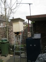
...yeah, I taped part of the holes like this:tape plus plumbers putty since the tape alone may be transparent to sound
...but that did nothing:
It was getting late so I had to break down. Maybe I'll try tomorow with something better.
Attachments
that cancellation null may be a red herring. Everybody who has done a synergy has had one but are they audible? Typically sharp narrow spikes aren't and this one is outside the passband.
turn on FDW = frequency dependent windowing 5 cycles and you won't even see it and so it won't distract you
Looking at your 2nd order XO, I'd say cut the tweeter level 2-3 db and then put in some EQ for that bump starting at 2500 Hz and it would look a lot better.
Is that dip at 250 Hz a floor/ground bounce null?
It's a very sharp notch, so I doubt you'll be able to hear it.
I assume you mean the dip at 350 Hz? It must be. I haven't seen it in other measurements (see above). I did however see something of a dip around 310 Hz, which I suspect is a panel resonance/soak in the box. And it wasn't this deep. There are still no braces yet 😱, which I expect/hope will help a lot.
Do you mean the 2nd order series crossover? (the 'original' crossover has a 2nd order high pass). I did have a resistor there to cut the level of the HF driver, but with 250W at 1 kHz I would've needed a 150W resistor. I figured that since I will be using active EQ anyway, I could correct this without using such a stupendous solution. Who would want a 150 W radiator inside of his speaker cabinet
 .
.Yeah Baby,
yer on the path...
I use it to replace two Titan48's. It's about the same size as one T48, but has double the output (admitted: you also need double the watts to do that). I built it with 12 mm birch multiplex and lots of bracing to keep the weight low. It still is noticably heavier than a T48, but I can still get it in and out of my car by myself. Sound is great, although different than the T48 and not as low as my drumrizer sub, but that is a LOT bigger sub. The T48 needs space to develop its sound ('long throw') For the space occupied I'm pretty happy with your Keystone designYeah Baby,
yer on the path...
 . Especially since I found a used but perfect B&C 18TBX46 (from a HK Audio Lucas 2000) for only €45 😎 (B&C replaced the TBX46 with the TBX100, so I figured it would work in the Keystone). I hope to be able to do a shootout with all of them this summer... I also hope you'll be able to finish the Keystone B-Low design before that (I have an 18TBW100 waiting on the shelf). You've had a pretty rough time the last couple of months. I hope that'll be over now
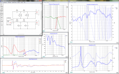
I've ran into a rather nasty problem with the series crossover:
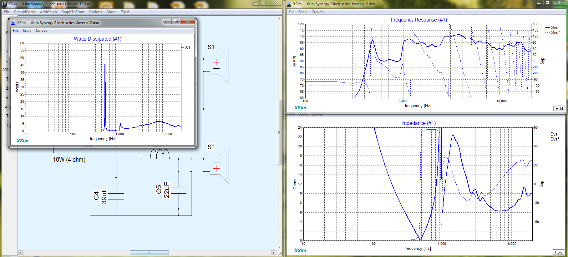
As you can see in these simulations things turn rather grim in case one of the drivers fails (which is not unthinkable in a live situation). In both cases (HF driver blown, woofers blown) the amp wil see a short circuit at certain frequencies, so if it's not properly protected, it's feedback-> HF driver blown -> amp blown 😡.
On top of that, if the woofers blow, the HF is likely to blow shortly after, as can be seen from the power dissipation chart, of course shortly followed by the amp 😱. NOT GOOD!
I think I'll be going back to a 'traditional' parallel crossover ...
Attachments
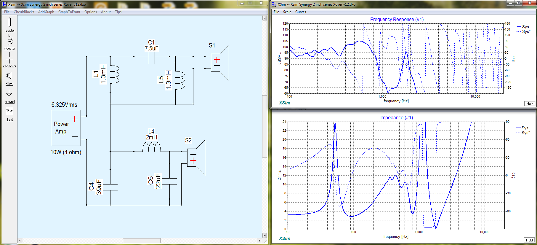
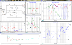
2nd try 🙂. Here's a crossover that has a 4th order highpass and a 4th order lowpass:
There's (much) more overlap than normal. I am trying to spare the HF driver as much as possible and have the woofers play as high as possible, so the HF driver gets less power in the lower regions, promising higher max SPL. That means a high Q in the lowpass section, also seen back as the dip around 900Hz in the impedance curve.
The step response (S1=HF driver, S2=woofers) looks ok (I think, let me know if it's not 😱), although maybe it would be better to have the HF peak a little delayed, as below.
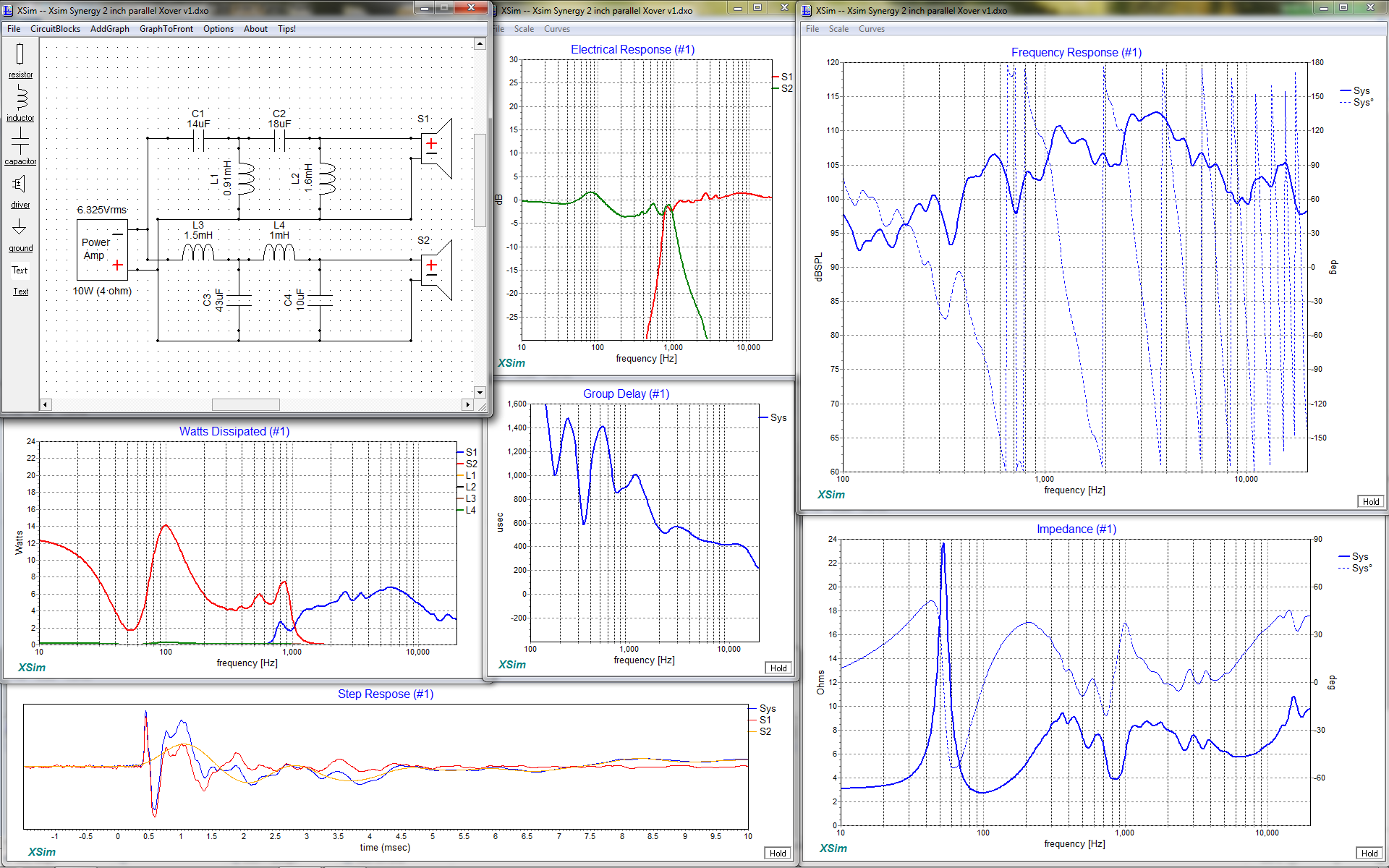
Building on this, I bypassed the 2nd L/C filter in the woofer section (turning it into a 2nd order filter) and played around with component values:

To me this looks a bit better than the first one. The frequency curve doesn't have the dip around 700 Hz and is more even in general, the woofer SPL fits better with the HF SPL (kind of symmetrical around the crossover point) and in the step response the HF driver peak is at about 1/3rd of the woofer peak. The impedance around the crossover point dips below 3 Ohms, but it isn't any lower than the lowest point in the woofer impedance curve. Also, the component values are pretty standard and are all in the E12 series, so no combining of components to get to the desired value would be necessary (saves money 😉).
There's (much) more overlap than normal. I am trying to spare the HF driver as much as possible and have the woofers play as high as possible, so the HF driver gets less power in the lower regions, promising higher max SPL. That means a high Q in the lowpass section, also seen back as the dip around 900Hz in the impedance curve.
The step response (S1=HF driver, S2=woofers) looks ok (I think, let me know if it's not 😱), although maybe it would be better to have the HF peak a little delayed, as below.
Building on this, I bypassed the 2nd L/C filter in the woofer section (turning it into a 2nd order filter) and played around with component values:
To me this looks a bit better than the first one. The frequency curve doesn't have the dip around 700 Hz and is more even in general, the woofer SPL fits better with the HF SPL (kind of symmetrical around the crossover point) and in the step response the HF driver peak is at about 1/3rd of the woofer peak. The impedance around the crossover point dips below 3 Ohms, but it isn't any lower than the lowest point in the woofer impedance curve. Also, the component values are pretty standard and are all in the E12 series, so no combining of components to get to the desired value would be necessary (saves money 😉).
Attachments
I'm (a bit) bummed. Yesterday I tried to set up an active crossover (using the DCX2496) to compare with the best passive crossover I had been able to come up with... and the active version sounded better 😛.
First I tried to find the 'sweet spot' for the crossover point... But24 @ 840 Hz for the woofer, But48 @ 878 Hz for the HF driver, woofer inverted, HF delayed by 0.40 ms. Then I tried tried to EQ as flat as possible (I don't really like an HF slope for listening volume, maybe for 'war volume') and I tried to match the frequency responses of both active and passive versions as closely as possible. Then a volume comparison to have both settings play equally loud. Then A/B listening, which was not really easy, because I still have only one prototype, so switching cables and settings in between. As I said, the active version sounded better. Not by a lot, but the sound 'just fell into place' better with that 0.4 ms delay on the HF.
So I tried to add an allpass filter to the simulation of the passive crossover. But that looks hideous. Also, I don't have the correct component values to try it out 😡. Which leaves me in a pickle: go analog and compromise (a little) on the sound but stay with my original idea: one 4-channel amp (RAM S6004) for tops + sub or go active and add another amp (more weight, expensive, etc.). Or I could keep the two options by adding another speakon, but that would be susceptible to operator error...
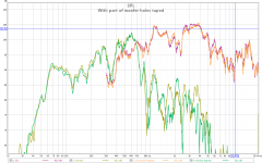
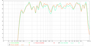
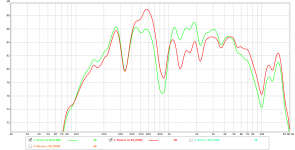
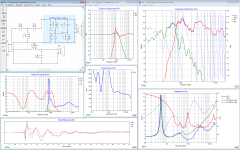
Anyway, here are some plots 😎. I think they are pretty self-explanatory using the legends. Btw, the dip around the crossover point is not always this deep, it depends on where the mic is. Plus these are done inside in a 'less than optimal' room. These are just that last measurements I had. I did have some flatter measurements, but didn't save them 😱.
First I tried to find the 'sweet spot' for the crossover point... But24 @ 840 Hz for the woofer, But48 @ 878 Hz for the HF driver, woofer inverted, HF delayed by 0.40 ms. Then I tried tried to EQ as flat as possible (I don't really like an HF slope for listening volume, maybe for 'war volume') and I tried to match the frequency responses of both active and passive versions as closely as possible. Then a volume comparison to have both settings play equally loud. Then A/B listening, which was not really easy, because I still have only one prototype, so switching cables and settings in between. As I said, the active version sounded better. Not by a lot, but the sound 'just fell into place' better with that 0.4 ms delay on the HF.
So I tried to add an allpass filter to the simulation of the passive crossover. But that looks hideous. Also, I don't have the correct component values to try it out 😡. Which leaves me in a pickle: go analog and compromise (a little) on the sound but stay with my original idea: one 4-channel amp (RAM S6004) for tops + sub or go active and add another amp (more weight, expensive, etc.). Or I could keep the two options by adding another speakon, but that would be susceptible to operator error...
Anyway, here are some plots 😎. I think they are pretty self-explanatory using the legends. Btw, the dip around the crossover point is not always this deep, it depends on where the mic is. Plus these are done inside in a 'less than optimal' room. These are just that last measurements I had. I did have some flatter measurements, but didn't save them 😱.
Attachments


There are a couple of different ways that you could introduce an allpass filter without having to do it passively but still use your passive crossover.
For testing if you have a computer then a plugin in could create the all pass function and you could tune it to work with your passive crossover.
Charlie Laub's Active Crossover Designer will give the biquad numbers for an all pass filter that you can use in an equaliser that accepts them.
The DCX may have all pass capability or programmed to use biquads, I don't really know though you would have to try it.
You can build an active all pass filter with an opamp and a few components. This could be inserted before your amp and then you would have active all pass but passive crossover.
Linkwitz describes the circuits here
Active Filters
I'd wouldn't be bummed so much as kicking myself for not having gone active sooner but then I don't care about weight and I've got a 1RU 8 channel amp 🙂
I don't mean for the rest of this to sound harsh or critical; its just my best advice based on a similar struggle. I know you are probably at the stage known as "having fun yet" but also that you will find all the effort worthwhile when you finally succeed.
While you are active, you should take another look at time alignment. If you have a mic position dependent dip at xo, then you haven't got point source behavior and that likely is because your drivers aren't time aligned. Also your step functions show serious misalignment. Ideally the step has a single sharp initial rise to a peak and then a gradual fall off. The sound will improve dramatically when you achieve this; its like a veil being lifted.
What is the correct time alignment? In my thread it was beaten into my head, that for a minimum phase XO like you have, the starts of each driver's IR should be aligned, not the peaks, with the XO and EQ filters in place and both drivers in the same polarity. So too was the process of EQing each driver's fall off to match a target curve.
If you go to the trouble of EQing each driver's frequency response curves to match your chosen Butterworth target curves for at least an octave past XO, then you can simply tune the DSP delay to find the delay that gives the flattest response through the XO. You might need higher order filters on one driver or the other to match the target slope; that doesn't matter so long as you hit the target curves. The filter group delays are taken into account when you adjust the DSP delay for time alignment and then later trim it for flattest transition through XO.
Now that you are setup to do active you should find then best solution and only then figure out what it takes to implement it passively and if that is worth the trouble. After all, a Behringer iNuke 1000 is only a couple of hundred bucks and weighs almost nothing. You could easily spend that much on passive components trying to optimize a passive XO.
I downloaded the spreadsheets yesterday and wasted 2 hours trying to get them to work, only to conclude late in the evening that my (apparently) Dutch version of Excel doesn't work with the English formulas in the sheet 😡😡Charlie Laub's Active Crossover Designer will give the biquad numbers for an all pass filter that you can use in an equaliser that accepts them.

 .
.It does have an all pass (per channel), so I will experiment with it (already did, but not very much).The DCX may have all pass capability or programmed to use biquads, I don't really know though you would have to try it.
Thanks for the hints and tips 😉!
I downloaded the spreadsheets yesterday and wasted 2 hours trying to get them to work, only to conclude late in the evening that my (apparently) Dutch version of Excel doesn't work with the English formulas in the sheet 😡😡
It does have an all pass (per channel), so I will experiment with it (already did, but not very much).
Thanks for the hints and tips 😉!
No problem 😉 Excel macros are a lot of fun!
If you need me to help you get it working or send you the biquad parameters for a given filter just send me a PM and I will run it for you on my version. I need to know the sampling rate you use as the values are only correct at one sample rate.
I thought it was a bit weird indeed. Thanks for pointing it out. I'll look into it.If you have a mic position dependent dip at xo, then you haven't got point source behavior and that likely is because your drivers aren't time aligned.
I am still reading into the whole step and impulse response stuff. To be honest, before yesterday I had no idea how the ideal (practical) step response of a speaker should look like. I always imagined it would be impossible for a multiway speaker to have a step response where you actually see only one step and no superimposed dips from the HF unit onto for example the woofer's step response (like I have now) 😱.Also your step functions show serious misalignment. Ideally the step has a single sharp initial rise to a peak and then a gradual fall off.
It's already sounding quite unveiling 🙂. I hope I'll get there 😀.The sound will improve dramatically when you achieve this; its like a veil being lifted.
I'm still (re)reading your whole Synergy corner horn thread. There's a lot of information in it 🙂🙂. Thank you for taking the time to help me out and point me in the right direction, John!In my thread it was beaten into my head, that for a minimum phase XO like you have, the starts of each driver's IR should be aligned, not the peaks, with the XO and EQ filters in place and both drivers in the same polarity.
That is also true, although the iNuke 1000 is a little weak. The CP850 can take 260W program (130 RMS) and I would like to have at least that to make sure there is enough overhead and the amp will never send a clipped signal to the 'fragile' HF driver. Inexpensive, good quality quad channel amps are hard to find. For my other Synergies I used Hypex amp modules and 'built' my own...Now that you are setup to do active you should find then best solution and only then figure out what it takes to implement it passively and if that is worth the trouble. After all, a Behringer iNuke 1000 is only a couple of hundred bucks and weighs almost nothing. You could easily spend that much on passive components trying to optimize a passive XO.
Thanks for your offer! I'd like to try and play with the sheets myself. The experience is half the fun, you know 😉. But if I don't manage, I may take you up on thatIf you need me to help you get it working or send you the biquad parameters for a given filter just send me a PM and I will run it for you on my version. I need to know the sampling rate you use as the values are only correct at one sample rate.
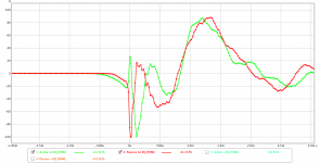
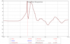
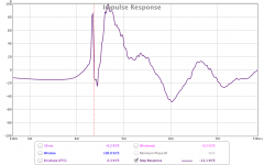
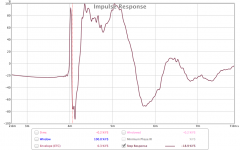
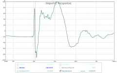
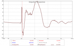
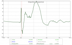
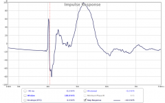
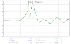
.I'm confused. I set out to determine a better alignment of the HF and LF section with the help of the Step response. But I don't see what the best Step response is 😱. There always seems to be a dip from the HF driver that shouldn't be there in an optimal Step response. And obviously, the more delay the HF driver gets, the more the sharp peak is delayed (shifted to the right). If I have to choose based on the best step response, I'd go for the '0 ms' curve. Would that be wise?
Setup was as follows:
On HF: EQ + crossover But48 @ 878 Hz, non-inverted
On LF: EQ + crossover But24 @ 840 Hz, non-inverted
Loopback used as timing reference. Mic about 1m in front of the mouth.
"-40ms" should actually be "-400 us" or "-0.40 ms", meaning the HF is delayed by -0.40 ms with regards to the woofers (actually, in this case the woofers are delayed by 0.40 ms). "0 ms" means there is no delay applied to any driver.
P.S.:
 .
.
Setup was as follows:
On HF: EQ + crossover But48 @ 878 Hz, non-inverted
On LF: EQ + crossover But24 @ 840 Hz, non-inverted
Loopback used as timing reference. Mic about 1m in front of the mouth.
"-40ms" should actually be "-400 us" or "-0.40 ms", meaning the HF is delayed by -0.40 ms with regards to the woofers (actually, in this case the woofers are delayed by 0.40 ms). "0 ms" means there is no delay applied to any driver.
P.S.:
I apologize, I'm really bad with names. I meant to say 'Jack', not 'John'Thank you for taking the time to help me out and point me in the right direction, John!
.Attachments
-
 REW Delay 40.png33 KB · Views: 72
 -
 REW Delay 30.png33.5 KB · Views: 75
 -
 REW Delay 20.png34.8 KB · Views: 79
 -
 REW Delay 10.png36.2 KB · Views: 73
 -
 REW Delay 0.png38.3 KB · Views: 414
 -
 REW Delay -10.png36.3 KB · Views: 411
 -
 REW Delay -20.png35.6 KB · Views: 420
 -
 REW Delay -30.png35.2 KB · Views: 425
 -
 REW Delay -40.png35 KB · Views: 428
 -
 REW Delay 50.png32.4 KB · Views: 74
Maybe I should invert polarity on the HF driver and regard the dip at the start (which is now a peak) as some sort of pre ringing?
The odd thing is: the SPL curves of all the above measurements are al (kind of) fine. There is no crossover notch in any of them...
The odd thing is: the SPL curves of all the above measurements are al (kind of) fine. There is no crossover notch in any of them...
actually, I thought "John" was your sig 🙂
10 ms steps are pretty large, both in terms of equivalent distance and the period of your XO frequency. I would repeat the process around 0 ms with smaller steps, no greater than 1/4 period of XO to get close and then walk it right in to within 10 usec. Perhaps you meant 10 microseconds? In that case I'm confused too. How do the IR "starts" of the separate drivers align?
10 ms steps are pretty large, both in terms of equivalent distance and the period of your XO frequency. I would repeat the process around 0 ms with smaller steps, no greater than 1/4 period of XO to get close and then walk it right in to within 10 usec. Perhaps you meant 10 microseconds? In that case I'm confused too. How do the IR "starts" of the separate drivers align?
All the steps for >=0 ms delay show what seems to be the sharp rise of the CD interrupting the slow rise of the woofer to a greater degree with increasing delay. Up until 0, it seems nothing happens until the CD starts up. So you want to delay the CD a little more or the woofer a little less until they both start up at the same time.
Based on that, I suspect the optimum delay is somewhere between 0 and -10 ms.
Based on that, I suspect the optimum delay is somewhere between 0 and -10 ms.
The steps were actually 0.1 ms, so 100 usec. I tried to explain that under the setup section of that post. I realise I could have used less confusing naming 😱.10 ms steps are pretty large, both in terms of equivalent distance and the period of your XO frequency. I would repeat the process around 0 ms with smaller steps, no greater than 1/4 period of XO to get close and then walk it right in to within 10 usec. Perhaps you meant 10 microseconds? In that case I'm confused too. How do the IR "starts" of the separate drivers align?
The starts can actually be seen in the above curves, the sharp spike being the HF driver.
- Status
- Not open for further replies.
- Home
- Loudspeakers
- Multi-Way
- Synergy horn for 135 dB+