?..Sure is a shame DaveS disappeared into the underworld.
diyAudio - View Profile: speaker dave - Last Activity: 29th March 2017
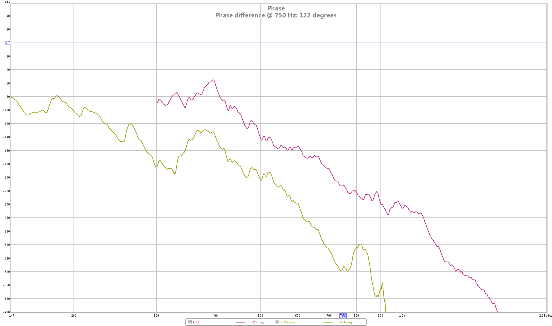
Yes, it is. 750(-ish).From the measurements, is your crossover somewhere in the 700-1k region?
So looking at the peak in the blue curve at 870Hz that should be down by 115 degrees I would want a delay ofThat would correspond to the little dip and peak in that region in the blue plot of the phase curve. You can calculate the approximate delay by knowing the jump in phase.
1 cycle at 700 Hz =700 cycles/second
Or, 360 degrees at 700 Hz = 1/700 seconds = 1.43 ms, i.e., it takes 1.43 ms for one complete cycle of 700 Hz.
So, for example, if you want to shift the phase by 50 degrees, delay = 1.43 x 50/360 ms
1/870 x 1000 x 115/360 = 0.367 ms (for the woofers)
What would also help is if you plotted individual driver responses with crossover so that you can see the phase overlap through the crossover.
Like this?
(both are shifted 2.22 ms to correct for delay of DCX2496 and distance of the microphone)
This thread is an excellent example of how it should be done:
Crossover mods for the AR4x - Mods, Tweaks, and Upgrades to the Classics - The Classic Speaker Pages Discussion Forums
What a good read! Thanks for that 😎.
Because of the dip in SPL I'm also looking into a different crossover configuration using Xsim (thanks Bill 😉 ). But that takes some time...
Sneak preview:
Attachments

Hi Thijs:
I got a lot of help getting my Synergies ("My Synergy Corner Horns and Bass Bins) time aligned and some of the advice I got in the thread of that name might help you. Others not, because I used active XO.
One thing in particular you might want to try. With your individual filtered driver measurements in REW you can simulate the effect of adding delay to the woofer. Go into the IR tab of the woofer measurement and press the controls button at the top right of the graph. In the top right of the control panel, you can add a time offset, which equals delay, calibrated in either time or distance. Now press the "All SPL" button to get display of both woofer and tweeter. Now you can use the control panel to do an A+B and/or A-B sum of the tweeter and the delayed woofer).
Play with the time offset in IR to find the delay that gives the best summation.
Hi Thijs,
Seems like the woofer has a very steep filter and the tweeter does not. Either that or woofer is not very well time-aligned with the tweeter. Can you try to wrap the phase so that we see just +180 to -180? That view is easier to read.
BTW, I should have mentioned that if you add a delay, you will change the phase everywhere, because the delay applies to all frequencies. If you want to just change the phase around the crossover, you have to play with the crossover slopes and points of the two drivers to get smooth overlap, as shown by speaker dave in that earlier thread. Unless you are using FIR filter, then you can change the phase anywhere you like.
That's a good one. I hadn't thought about it that wayHi Thijs:
I got a lot of help getting my Synergies ("My Synergy Corner Horns and Bass Bins) time aligned and some of the advice I got in the thread of that name might help you. Others not, because I used active XO.
One thing in particular you might want to try. With your individual filtered driver measurements in REW you can simulate the effect of adding delay to the woofer. Go into the IR tab of the woofer measurement and press the controls button at the top right of the graph. In the top right of the control panel, you can add a time offset, which equals delay, calibrated in either time or distance. Now press the "All SPL" button to get display of both woofer and tweeter. Now you can use the control panel to do an A+B and/or A-B sum of the tweeter and the delayed woofer).
Play with the time offset in IR to find the delay that gives the best summation.
 . I did use that function for the above two phase curves. Thanks 😉.
Hi Thijs,
Seems like the woofer has a very steep filter and the tweeter does not. Either that or woofer is not very well time-aligned with the tweeter. Can you try to wrap the phase so that we see just +180 to -180? That view is easier to read.
BTW, I should have mentioned that if you add a delay, you will change the phase everywhere, because the delay applies to all frequencies. If you want to just change the phase around the crossover, you have to play with the crossover slopes and points of the two drivers to get smooth overlap, as shown by speaker dave in that earlier thread. Unless you are using FIR filter, then you can change the phase anywhere you like.
Actually the woofer did have just a first order filter (just one inductor of 0.47 mH). What you are seeing in SPL drop is the synergy bandpass effect. I really have no idea where the steep phase change comes from 😕.
Phase wrapped:
I'm still aiming for a passive crossover, so FIR is kind of impossible. I'm determined to play around with components until I get it right (or good enough 😱). So I'm not done yet 🙄.
(and off course thank you all for contributing and your suggestions/guidance!)
Attachments
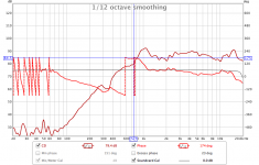
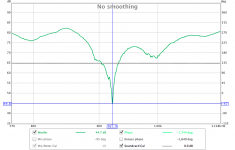
Turns out that 922 Hz ~ 37.3 cm is double the distance from the center of the offset horn entry points to the origin of the hornI really have no idea where the steep phase change comes from 😕.
 , thus a cancellation node seems to be the source of it. There is also a dip in the frequency response there, clearly viewable when smoothing is turned off.
Attachments
Try reversing polarity on the HF driver.Turns out that 922 Hz ~ 37.3 cm is double the distance from the center of the offset horn entry points to the origin of the horn
The curve is with only the woofers connected, not the whole system. The HF driver wasn't even connected...Try reversing polarity on the HF driver.
yes, as should have been expected, your woofer has a cancellation null at 922 Hz and you are crossing over from woofer to tweeter around 700 Hz, IIRC, so it shouldn't be a problem.
The cancellation null doesn't explain phase steps around XO, if that is what you are implying.
The cancellation null doesn't explain phase steps around XO, if that is what you are implying.
That makes sense. Reflections will cause sharp changes in phase. The solution is to move to the woofer entrance closer to push the reflection higher in frequency or move the crossover lower so that the dip is outside the passband of the woofer. Or, make a steeper crossover so that even with the 700 Hz crossover point, the woofer output is diminshed by the time it gets to 900 Hz. Maybe Bill and others with actual synergy build experience can offer some solutions.
I probably can't offer a lot. I've always taken the easy way out, putting the midrange driver(s) as close as humanly possible to the tweeter diaphragm!
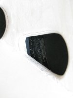
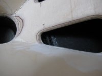
It does indeed look close. That being the case, why is the reflection null at such a low frequency? 922 Hz corresponds to a ~7" round trip or 3.5" one way. I guess I can believe that given how elongated the woofer hole is.
You can move the hole closer by blocking off the front part of the hole. That will also change the bandpass peaking, which might even help. If you shorten it too much, then you might have noise problems at high SPL. But the problem isn't just a case of making sure the hole is large enough; the hole size works with the horn wall thickness to shape the high end of the response.
But 922 Hz is out past the XO so it should work provided the XO LPF has steep enough slopes. What I would do is go active at least temporarily and find the dsp delay and filter slopes that work. Then at least you will have a better idea of what shape your passive XO should take.
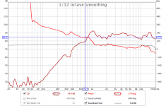
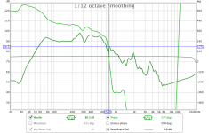
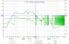
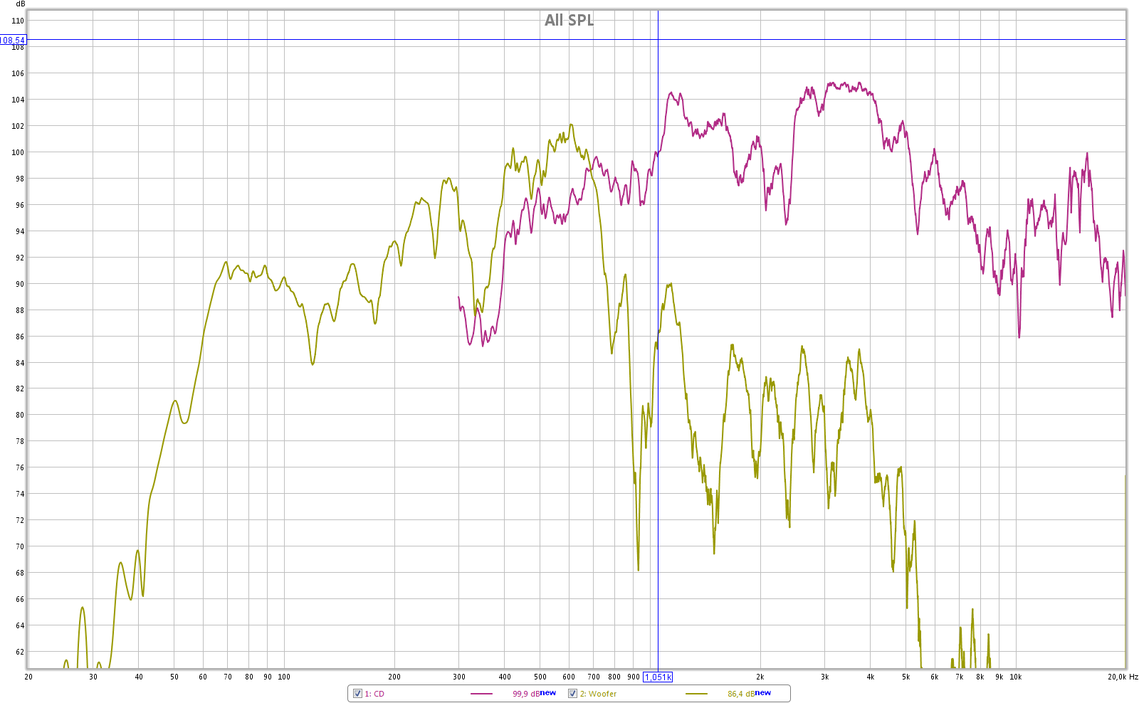
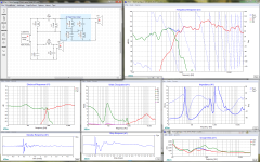
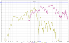
I redid some measurements outside. I figured I could measure the delay (and thus the offset) between HF driver and woofers using REW's loopback function as a timing reference (duh 😱). Here are the results:
SPL (unfiltered):
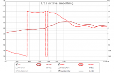
Delay (substracted 4.286 ms to correct for AD/DA delay and distance to the mic):
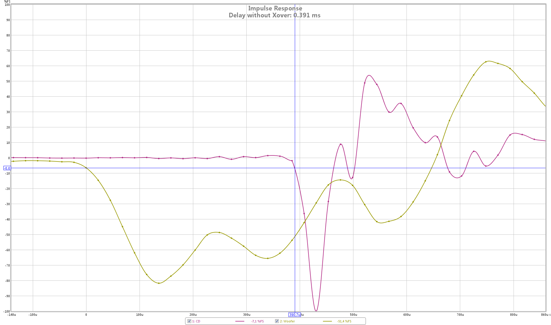
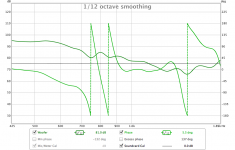
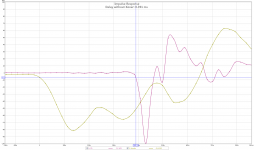
...and step response:
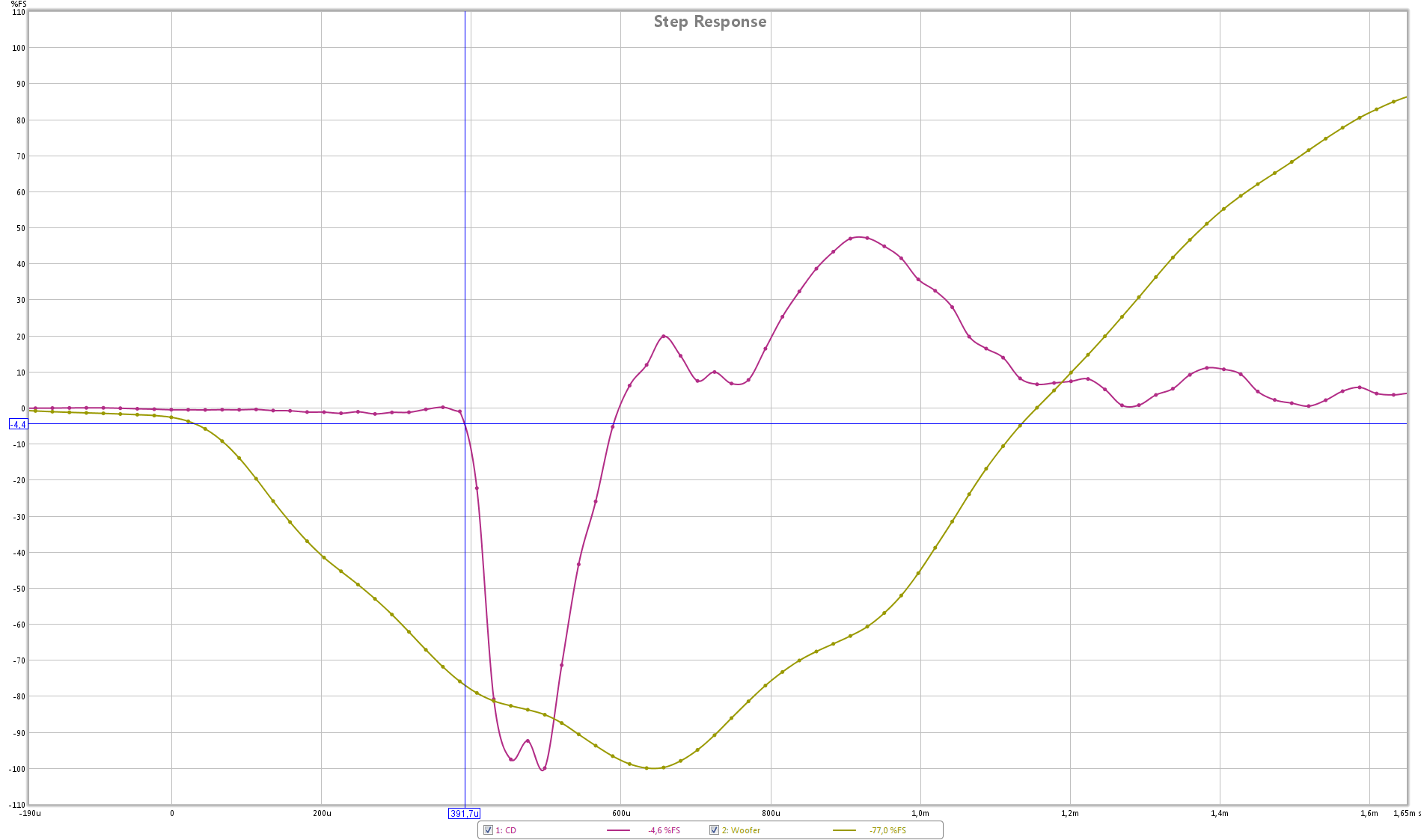
(looks like somewhere in the measurement chain the polarity is reversed)
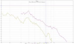
The above (delay corrected) leads to the following phase responses:
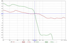
Using the new measurements I did some crossover simulations with Xsim (really neat little program 😎). Here is the 'original' crossover:
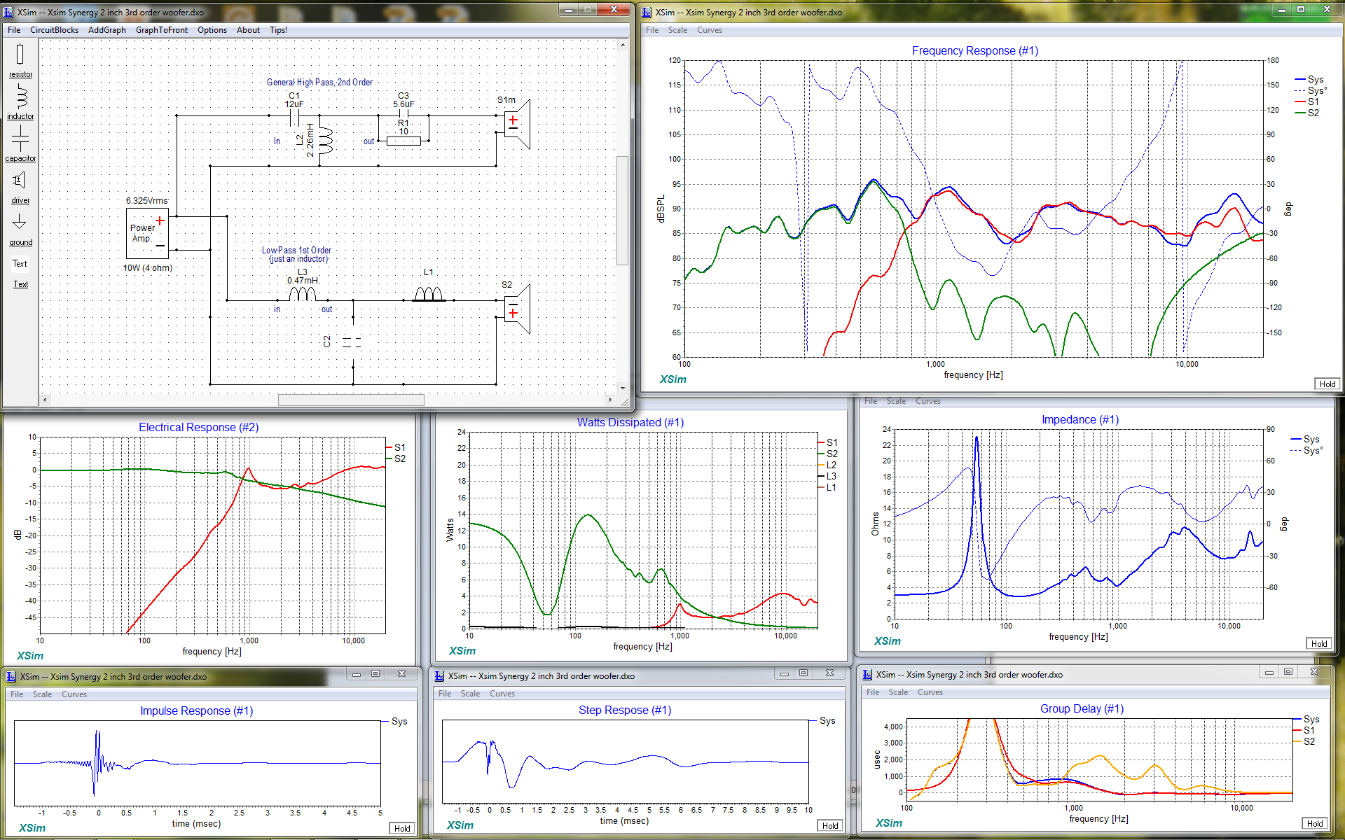
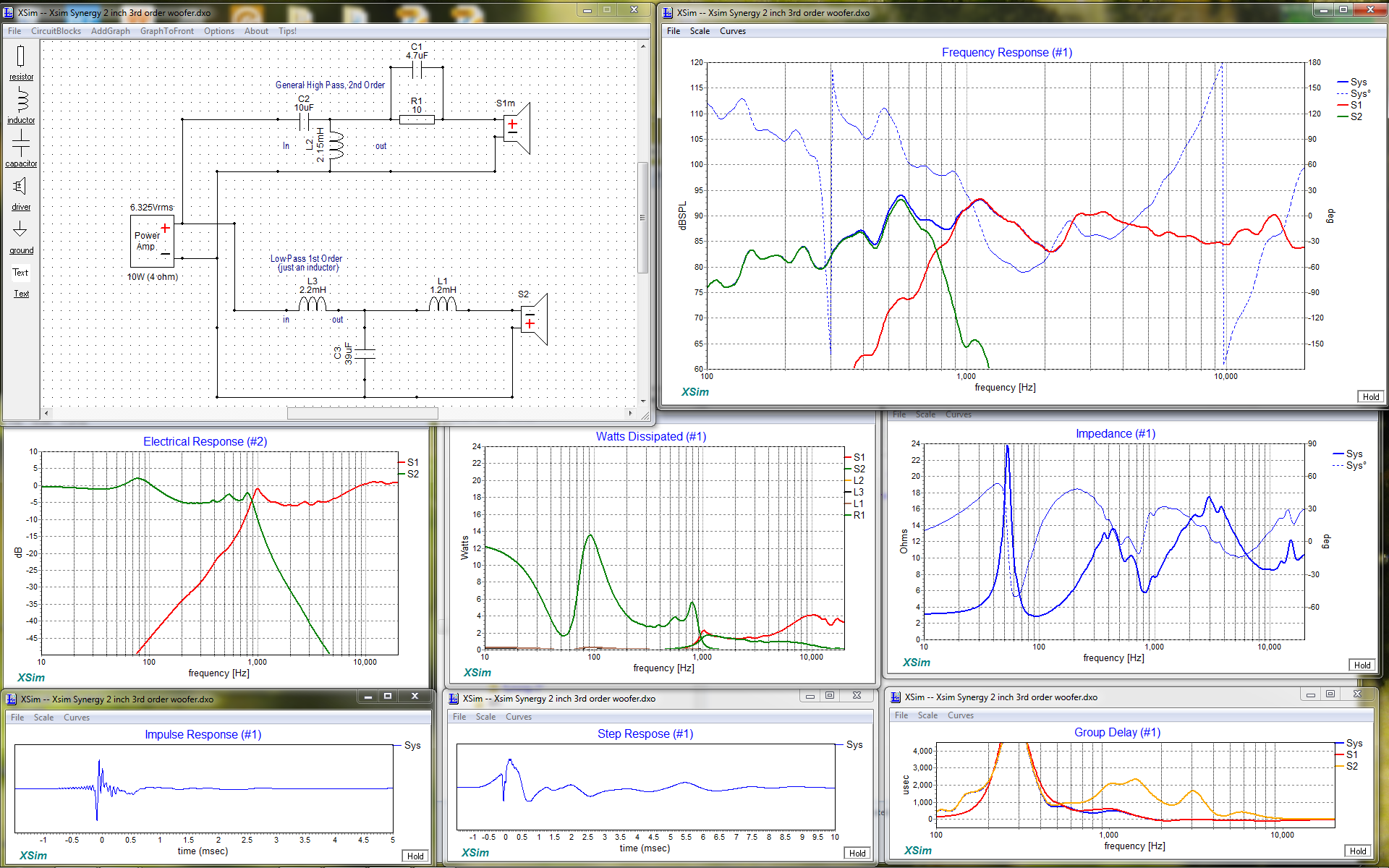
3rd order for the woofer:
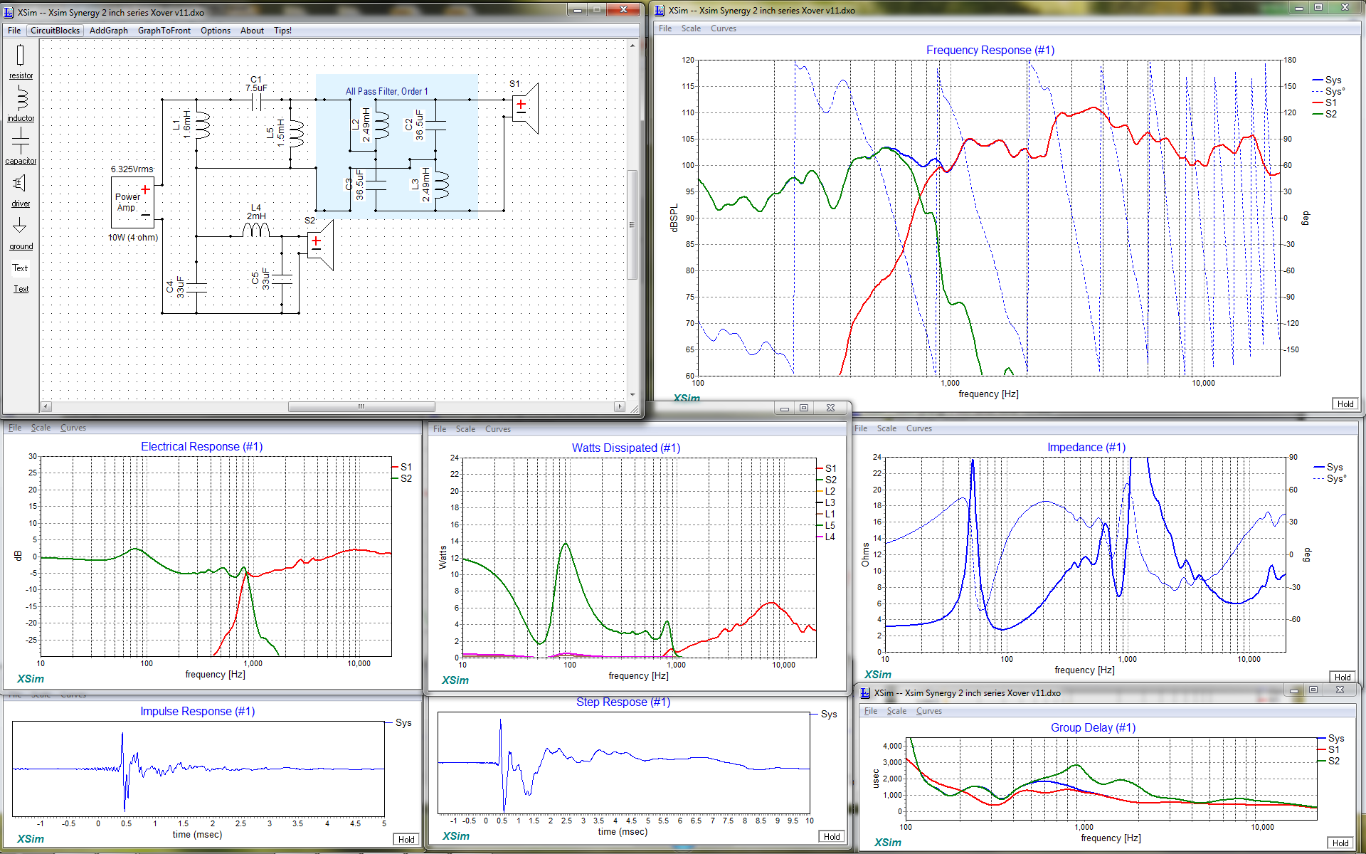
Series crossover (2nd order):
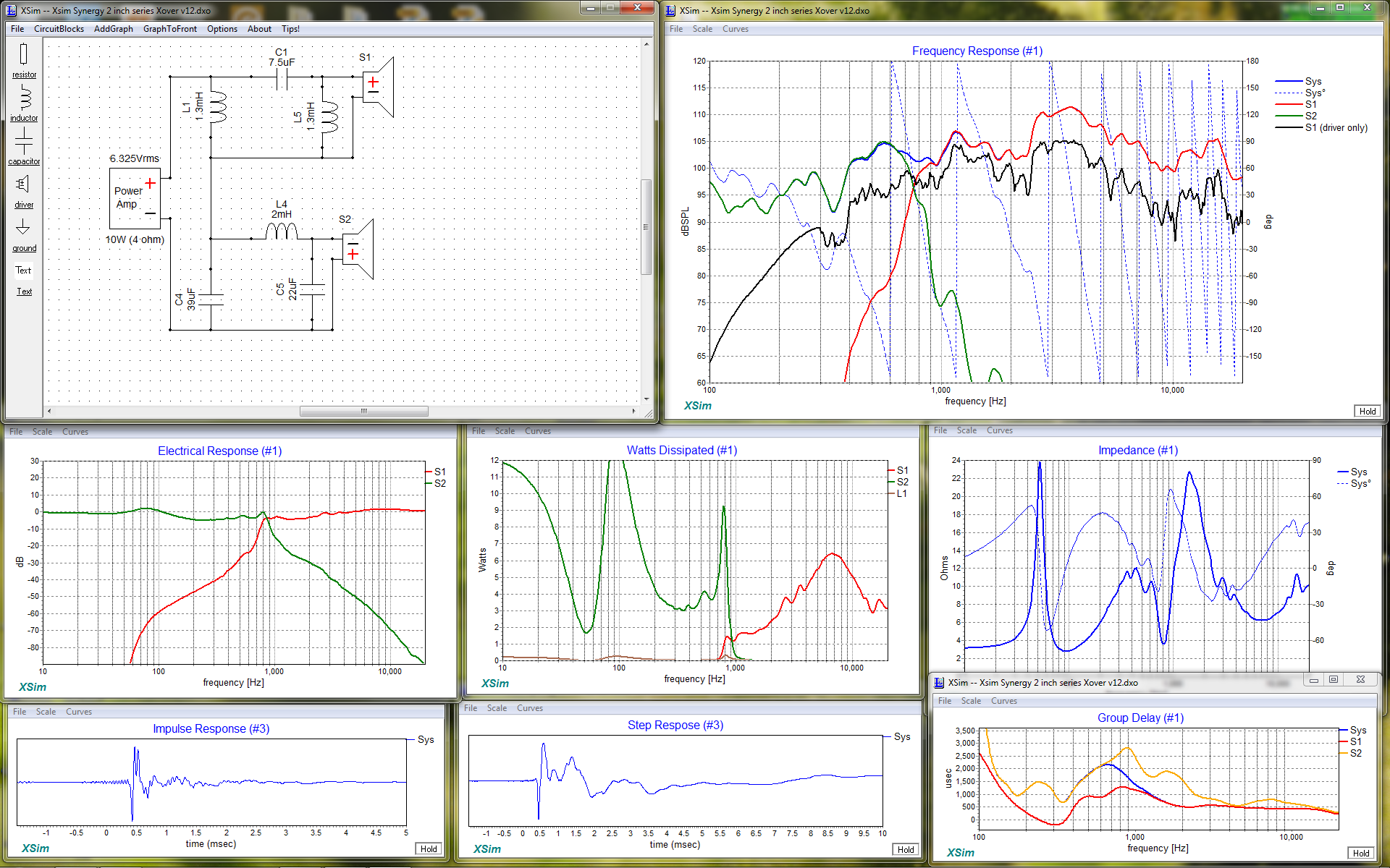
And, looking at the delay in the image above, with a delay on the HF driver:
Still have to analyse the outcomes. There is kind of a lot of information to look at 😱.
Hit me with your thoughts 😉
SPL (unfiltered):
Delay (substracted 4.286 ms to correct for AD/DA delay and distance to the mic):
...and step response:
(looks like somewhere in the measurement chain the polarity is reversed)
The above (delay corrected) leads to the following phase responses:
Using the new measurements I did some crossover simulations with Xsim (really neat little program 😎). Here is the 'original' crossover:
3rd order for the woofer:
Series crossover (2nd order):
And, looking at the delay in the image above, with a delay on the HF driver:
Still have to analyse the outcomes. There is kind of a lot of information to look at 😱.
Hit me with your thoughts 😉
Attachments
-
 Xsim parallel Xover 1st order.png366 KB · Views: 727
 -
 Xsim parallel Xover 3rd order.png364.7 KB · Views: 732
 -
 Xsim series Xover without delay.png484.2 KB · Views: 722
 -
 Xsim series Xover with delay.png322 KB · Views: 718
 -
 rew outside spl (ir corrected).png120.8 KB · Views: 725
 -
 rew outside delay (ir corrected).png90.7 KB · Views: 728
 -
 rew outside step (ir corrected).png80.2 KB · Views: 721
 -
 rew outside phase (ir corrected).png78 KB · Views: 736
Yes, it's about 19 cm from the HF driver's diagram to the center of the port...It does indeed look close. That being the case, why is the reflection null at such a low frequency? 922 Hz corresponds to a ~7" round trip or 3.5" one way. I guess I can believe that given how elongated the woofer hole is.
I worry a bit about port noise at high volumes, That's why they are larger than a typical Synergy midrange port. I realize it's a comprimise. It also influences the HF driver and is probably responible for the suckout around 2 kHz. I will try some tape on the holes to make them smaller and see what happens.You can move the hole closer by blocking off the front part of the hole. That will also change the bandpass peaking, which might even help. If you shorten it too much, then you might have noise problems at high SPL. But the problem isn't just a case of making sure the hole is large enough; the hole size works with the horn wall thickness to shape the high end of the response.
Exactly. I was hoping to get away with it 😉But 922 Hz is out past the XO so it should work provided the XO LPF has steep enough slopes.
that cancellation null may be a red herring. Everybody who has done a synergy has had one but are they audible? Typically sharp narrow spikes aren't and this one is outside the passband.
turn on FDW = frequency dependent windowing 5 cycles and you won't even see it and so it won't distract you
Looking at your 2nd order XO, I'd say cut the tweeter level 2-3 db and then put in some EQ for that bump starting at 2500 Hz and it would look a lot better.
Is that dip at 250 Hz a floor/ground bounce null?
- Status
- Not open for further replies.
- Home
- Loudspeakers
- Multi-Way
- Synergy horn for 135 dB+