1) Yes, the side "wings" have a 90 degree bracket cut from "2x4" lumber.
2) If you want the two cabinets to be within 1/4 wavelength at 106 Hz, they need to be side by side, with wings on either side. The wings are simply "barn doors", the depth can be as shallow as you like, as long as it still stands by itself in a moderate breeze before attachment with whatever method you choose.
At 106 hz, the cabinets can be distanced 80 cm(as the 106 hz wave is 3.2m long) from each other without destructive interference in the upper region, which happen to be almost dead on if I have one waveguide per your plan for every cabinet, placing them as close as possible.
True, for one pair.At 106 hz, the cabinets can be distanced 80 cm(as the 106 hz wave is 3.2m long) from each other without destructive interference in the upper region, which happen to be almost dead on if I have one waveguide per your plan for every cabinet, placing them as close as possible.
With the approach I suggested in Post #101 you could "V" load 4 cabinets and use a single pair of wings with more frontal area and gain, yet still be within 1/4 wavelength.
Very cool horn extensions! I am not saying I have learned HR but I am grasping it, and there was a time I didn't think I ever would... Best of luck.Yes i guess there is no way out...
Need to learn HornResp :O
Last time when i tried to sim the RCF LF18X451 in the keystone it didnt turn out well...
So i cant imagine how it will go trying to simulate this monster horn...
I think i could learn russian and chinese before i learn horn resp hehehe
But OK
Here we go!!!
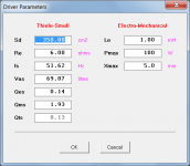
For entering driver data: enter Sd first / double-click on Cms and enter Vas / double-click on Mmd and enter Fs / enter Re and Le / double-click on Rms and enter Qms / double-click on Bl and enter Qes /// to check: double-click on Sd, and a window will show what was entered, and what Hornresp calculated, also, here we can enter Pmax and Xmax.
Alternatively, simply double-click on the Sd input box in Edit mode and enter the Thiele-Small parameter values directly into the Driver Parameters form, and then close the form by clicking the OK button. The driver electro-mechanical parameter values on the main input form will update automatically to reflect the entered Thiele-Small values.
Attachments
The results match that of mine where the saddle shape FR emerges when using an extension. It appears the mouth size of the final exit somewhat affects this but not completely. Curious what it takes to fix this. I suspect a sub with a rising FR would do better but have not simmed any YET.Hi Jesperino,
You are designing a whole new enclosure. You could try to simulate this in Hornresp using the TH1 Driver Arrangement. I'll attach a quick stab at this, I made no attempt to arrive at a design or accurate numbers, just move the sliders around in the Wizard, and see what happens.
Regards,
A little update on my (tapped) horn extension research.
Conclusion for now is:
ONE DOES NOT SIMPLY EXTEND A TAPPED HORN!!!
Seems like that even if you extend the hornpath of a tapped horn you wont get any lower response... Atleast not if you like in this example just extend the hornpath of the keystone.
Because its rather the distance from the front point of the driver until the point where it meets the backpart of the driver that will determine how deep your response will be.
(please correct me if im wrong)
For the exact same reason it makes so much sense that making the keystone taller is what will give you the lower extension because the distance from front of driver to back of driver is increased.
But this kind of extension that i had in mind would only work for fx a Front Loaded Horn
(Maybe some other horns as well?)
So... For tapped horns seems like you can only gain extra decibels with extensions and waveguides.
Thats also not a bad deal -Who doesnt want extra decibels???
At least i learned some more about the topic
I just really liked the idea that a "simple" extension could get you a lower response.
But for now "project extension" is gonna be on standby
Bought materials for constructing 2 more Keystones 🙂
Thanks to Zwiller and tb46 for answering some PM`s 🙂
Jesperino,1)Because its rather the distance from the front point of the driver until the point where it meets the backpart of the driver that will determine how deep your response will be.
2)For the exact same reason it makes so much sense that making the keystone taller is what will give you the lower extension because the distance from front of driver to back of driver is increased.
3)So... For tapped horns seems like you can only gain extra decibels with extensions and waveguides.
1)The horn path length on both TH and FLH determines the LF "depth".
2) Making the Keystone exit taller (more area) increases the LF corner frequency (a higher cut-off), making the cabinet taller, thereby increasing path length, lowers the low corner cutt off frequency.
3) A "horn extension" will increase path length, which lowers the low corner, but that will come at a reduction of sensitivity-lower response is not as loud (Hoffman's Iron Law). Extending a TH also will lower the upper peak/dip.
A "waveguide", AKA "barn doors", increases the frontal boundary, which increases forward directivity, the additional forward gain has a smoothly rising response with frequency.
Art
Not sure there is a simple method to produce this. I would use HR to sim some things. It might be more interesting clamping plywood onto 2 boxes and fooling around! Based on the sims I did the effect should be obvious but have not tried it yet myself.
Hi Zwiller,Not sure there is a simple method to produce this.
Actually there is, if the extender increases the pathlength with 0.6 of the radius of the mouth area it needs doubling the mouth area for the 'new' extender-mouth.
Regards,
Djim
Hi Zwiller,
Actually there is, if the extender increases the pathlength with 0.6 of the radius of the mouth area it needs doubling the mouth area for the 'new' extender-mouth.
Regards,
Djim
Thank you. Is this the minimum or optimum and/or is this basic horn loading theory?
Extend the horn in what way?Which parameters must I change in Hornresp to extend the horn?
Most designs (Keystone included) use all 5 available segments of hornresp to simulate with decent accuracy. To simulate an extension you'll need to either use only 4 segments knowing that it will compromise the accuracy of the simulation, or use akabak which does not have a practical limit on number of segments.
If you really want to increase the output of a tapped horn you should add a front-resonator instead of a flared hornsection.
This is the THAM15 coupled to a large front-resonator:

This is the idea we use in our new ROAR-series of bass horns.
Martinsson's Blog - ROAR family overview
This is the THAM15 coupled to a large front-resonator:
This is the idea we use in our new ROAR-series of bass horns.
Martinsson's Blog - ROAR family overview
Can you explain further, and also upload up pictures for reference. e.g THAM15 with front-resonator.
In the same way you can add a ported chamber to the front of a bassreflex box and get a 6th order seriestuned bandpass, you can add a quarter-wave resonator to the front of a tapped horn, tapped pipe, sealed box or bassreflex box.

There are more pictures of my ROAR12 build on Martinssons blog (link in my last post).
If you add a front-resonator to the THAM15, the resonator can be detachable and hinged in the corners and foldable for transport. It is just a huge duct with a large cross-section and the right length to create a quarter wave resonance centered at the dip in the midbass respons of the THAM.
The quarterwave resonator has a wide enough resonant bandwidth to increase the efficiency of the whole bandwidth of the tapped horn - and even widen it somewhat which you can see in the simulation I posted in my previous post.
Cheers,
Johannes
Extend the horn in what way?
Most designs (Keystone included) use all 5 available segments of hornresp to simulate with decent accuracy. To simulate an extension you'll need to either use only 4 segments knowing that it will compromise the accuracy of the simulation, or use akabak which does not have a practical limit on number of segments.
In my research into this, I saw many good discussions on the matter with very knowledgeable folks and apparently it's not really an issue. Just combine a segment so you have another one to use.
If you really want to increase the output of a tapped horn you should add a front-resonator instead of a flared hornsection.
This is the THAM15 coupled to a large front-resonator:
View attachment 609894
This is the idea we use in our new ROAR-series of bass horns.
Martinsson's Blog - ROAR family overview
Thank you! Interesting stuff. The ROAR line looks like a winner.

Here is a better balanced version of the resonator-enhanced THAM15.
A shorter resonator with larger cross-section.
It adds 7 dB efficiency at 80 Hz, the center of the midbass "kick".
Many THs have a dip in the response in the midbass, where you usually would want a small peak to accentuate the midbass "punch" and energy.
Thank you! Interesting stuff. The ROAR line looks like a winner.
Thanks! I have built a ROAR12 and I like it a lot. I have not run it in any live venue. I hope I will get my MiniDSP and Umik tomorrow so I can take some measurements.
Cheers,
Johannes
Yes, I am with you that dip/saddle shape FR.View attachment 609997
Many THs have a dip in the response in the midbass, where you usually would want a small peak to accentuate the midbass "punch" and energy.
Thanks! I have built a ROAR12 and I like it a lot. I have not run it in any live venue. I hope I will get my MiniDSP and Umik tomorrow so I can take some measurements.
Cheers,
Johannes
Best of luck on testing!
Do you see a problem with 2 cabs sharing a resonator? IE 2 THAM15s on their side, mouths facing each other and a panel on top and one on the bottom connecting them, creating the resonator with the ground plane.
- Home
- Loudspeakers
- Subwoofers
- Horn Extender/Wave-guide for TH