About 20 minutes later I see cops walking around and they ask if I heard a gunshot... Showed them the carnage, we laughed, they said they'll tell the office they didn't find anything, and I said thanks.
Why?!
Is it illegal to solder amps, if you said them "Thanks"?
You know how apartment staff can be. "Oh there is smoke in here that's going to mean no deposit refund."
There have been so many kabooms in my work room that minor poofage or the smell of burnt parts doesn't usually even draw attention. There have been exceptions though.
Somewhere in the early days of the DIY PC craze (mid to late 1980's) myself and several other tech minded people started making the rounds of the local PC clone shops and asking to talk to their tech guy. If we decided that he was typical (minimal real knowledge) we would offer to buy their defective or returned merchandise for something like 10 cents on the dollar. We would sort out the good stuff and sell it or build PC's and sell them.
After several years of doing this we had a warehouse full of stuff that was really dead. I decided to pick a board or part we had lots of, and spend a day on each fixing, or making a few good ones out of many bad ones by mixing and matching parts.
Then one day it was power supply time. I had over a hundred PC power supplies that didn't work. I made a simple test fixture out of a car headlight (dummy load) and 3 voltmeters. The most common defect was just a blown fuse inside the unit usually mounted on the PC board. I started opening them up, jumping the fuse with a clip lead, and plugging them in. If it worked it got a new fuse if it didn't it went into the $1 box for the next hamfest.
I was happily zipping through power supplies reclaiming 30% or so dead ones using this technique when IT happened.......you know what's next.....KABOOM!!!!! I stuck the plug in the wall and instantly I knew there was something really wrong because the room lights dimmed. Before I could get that plug out (it seemed stuck) there was a BIG BANG. One of those 200 uF 400 volt caps exploded with enough force to rip other parts off the PC board and embed a chunk of the aluminum can in the sheetrock ceiling......Some of it was still there when I sold the house 25+ years later. Needless to say, power supply day was over, and I had to modify my technique when it resumed several days later. I added a 500 watt light bulb in series with my fuse "shunt."
Sometimes my tube amp experiments scare even me. DONT TRY THIS AT HOME.....WE ARE TRAINED PROFESSIONALS!!!! (yeah, where have I heard this before)
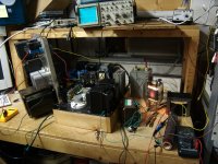
This was a test amp that I assembled to evaluate a prototype OPT. It was made by substituting a 500 watt 833A triode for the 100 watt 845 triode in my 845SE amp, and substituting a 1500 volt 1/2 amp power supply for the 1050 volt unit in the amp......all with hamfest grade Chinese clip leads. Note the vice grip and hose clamps tube socket.
I had a 1/4 inch Lexan blast shield between myself and the amp and a fire extinguisher at my feet at all times whenever the amp was powered up, except for one picture session from a safe distance. This guy cranked out 200 watts in SE but didn't quite make the grade as a HiFi amp, so.....I plugged in a guitar preamp and did my best to blow it up.....it survived a week of my abuse and the only hiccups was a tripped 15 amp bench breaker twice. Then my sanity returned, an I took it apart.
Somewhere in the early days of the DIY PC craze (mid to late 1980's) myself and several other tech minded people started making the rounds of the local PC clone shops and asking to talk to their tech guy. If we decided that he was typical (minimal real knowledge) we would offer to buy their defective or returned merchandise for something like 10 cents on the dollar. We would sort out the good stuff and sell it or build PC's and sell them.
After several years of doing this we had a warehouse full of stuff that was really dead. I decided to pick a board or part we had lots of, and spend a day on each fixing, or making a few good ones out of many bad ones by mixing and matching parts.
Then one day it was power supply time. I had over a hundred PC power supplies that didn't work. I made a simple test fixture out of a car headlight (dummy load) and 3 voltmeters. The most common defect was just a blown fuse inside the unit usually mounted on the PC board. I started opening them up, jumping the fuse with a clip lead, and plugging them in. If it worked it got a new fuse if it didn't it went into the $1 box for the next hamfest.
I was happily zipping through power supplies reclaiming 30% or so dead ones using this technique when IT happened.......you know what's next.....KABOOM!!!!! I stuck the plug in the wall and instantly I knew there was something really wrong because the room lights dimmed. Before I could get that plug out (it seemed stuck) there was a BIG BANG. One of those 200 uF 400 volt caps exploded with enough force to rip other parts off the PC board and embed a chunk of the aluminum can in the sheetrock ceiling......Some of it was still there when I sold the house 25+ years later. Needless to say, power supply day was over, and I had to modify my technique when it resumed several days later. I added a 500 watt light bulb in series with my fuse "shunt."
Sometimes my tube amp experiments scare even me. DONT TRY THIS AT HOME.....WE ARE TRAINED PROFESSIONALS!!!! (yeah, where have I heard this before)
This was a test amp that I assembled to evaluate a prototype OPT. It was made by substituting a 500 watt 833A triode for the 100 watt 845 triode in my 845SE amp, and substituting a 1500 volt 1/2 amp power supply for the 1050 volt unit in the amp......all with hamfest grade Chinese clip leads. Note the vice grip and hose clamps tube socket.
I had a 1/4 inch Lexan blast shield between myself and the amp and a fire extinguisher at my feet at all times whenever the amp was powered up, except for one picture session from a safe distance. This guy cranked out 200 watts in SE but didn't quite make the grade as a HiFi amp, so.....I plugged in a guitar preamp and did my best to blow it up.....it survived a week of my abuse and the only hiccups was a tripped 15 amp bench breaker twice. Then my sanity returned, an I took it apart.
Attachments

Just for fun...
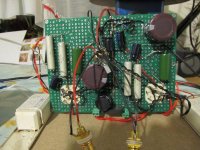
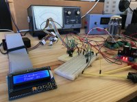
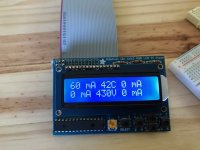
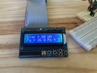
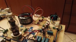
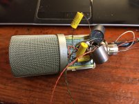
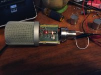
This is to be my first fixed bias PP amplifier, and I was wondering what to do about bias adjustment/control, so have developed this micro based controller that will also end up controlling audio input selectors etc. It is Raspberry Pi based using Python 3 script; 4 ADC's to measure the 4 tube currents and 4 DACs to control the grid bias using a simple level translator circuit.
It works very well - you dial up a new bias and within 2 iterations the new bias is set to within 0.5mA. Only 1 tube is connected at this time. I use the Koren model of the triode connected tube to help get to the new bias point quickly. Also using the measured B+ voltage I compensate for Vg on the fly to ensure Ia stays stable.
Attachments


Very neat! I'm thinking of making a tube curve tracer using a microcontroller. My workshop is almost done and I'll actually have a place to work on that soon.
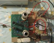
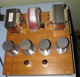
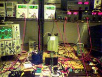
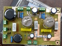
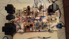
Testing the power supply and all-tube regulator for my PPP KT88 amp. Regulator provides 353V for drivers and 270V for the output tube screens. I was impressed that the driver regulator (that has about 60 dB of loop gain) had very low output noise and very low drift. Heaters are DC except the pass tubes, that have their own transformer on the PC board.
Attachments

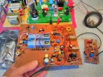
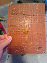
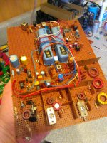
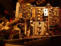
One of my first "complex" projects - most of a single band ssb / cw transceiver. The main board is slightly larger than the Tubelab SSE board. The carrier oscillator board is off to the right, the digital display stuff off to the left in the anti static bag. The HFO is not shown - started with an LC oscillator, and then a "sorta synthesizer" with a VCO at the injection frequency phase locked to a very stable low frequency oscillator.
Pretty straightforward - the matched USB and LSB mechanical filters makes frequency management easy. No need to shift the carrier oscillator frequency or offset the display to read properly. CW is handled by a tone ran through the USB filter. Puts out a couple of watts PEP. The idea was to use this as a low frequency tunable IF for transverters, But most of the RX is on one chip - a Nat Semi LM 373, and I was never satisfied with the signal to noise ratio from it.
I moved on to an FM transceiver, and then some other stuff, and just never revisited this. I didn't need any of the parts, so it never got torn down. I still like using matched filters, but I acknowledge, grudgingly, that SDR is the way of the future, and I have some extremely simple SDR chips and am slowly working on an extremely simple SDR VHF rig.
Oh, this is an audio board? Well then, the mic input is a bipolar 2N2222 feeding an MC1496 balanced modulator, and the audio is another 2N2222 feeding an LM386-4 for the power stage.
Win W5JAG
Attachments
Very neat! I'm thinking of making a tube curve tracer using a microcontroller. My workshop is almost done and I'll actually have a place to work on that soon.
Like this?
ANALYSEUR / VACUUM TUBE CURVES TRACER - ANALYZER - LAMPEMETRE TRACEUR DE COURBES
QRP?
Off the mainboard, yes.
TX path:
mechanical filter -> MPF102 -> SN76514 balanced mixer -> bandpass filter ->
2N3563 -> 2N3553 -> 2SC1909
So, 2 or 3 watts PEP. About as simple as one can be made, and be usable on the air.
Win W5JAG
Attachments
Dug up some pics of older stuff.
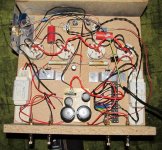
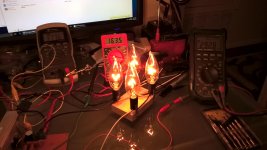
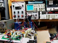
First pic is a solid state high voltage regulator for a tube amp(bottom left corner) driving 4 series 120V 40W bulbs as a dummy load. 377V input(tested up to 600V) and 292V output at 200+mA. Uses a BUF11 around an LM317. Worked well but didn't want the big heatsink so I think I'm going to have the LM317 drive some 7233s instead to make it glow and keep the heat above the chassis.
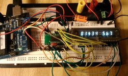
Second pic is an Arduino driving a VFD from a calculator.
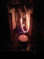
Third pic is me lighting up some nichrome in a jar with a candle for eating up oxygen. Tungsten worked but not for long. Daughter wanted to see what the inside of an incandescent light looked like when it was on.
First pic is a solid state high voltage regulator for a tube amp(bottom left corner) driving 4 series 120V 40W bulbs as a dummy load. 377V input(tested up to 600V) and 292V output at 200+mA. Uses a BUF11 around an LM317. Worked well but didn't want the big heatsink so I think I'm going to have the LM317 drive some 7233s instead to make it glow and keep the heat above the chassis.
Second pic is an Arduino driving a VFD from a calculator.
Third pic is me lighting up some nichrome in a jar with a candle for eating up oxygen. Tungsten worked but not for long. Daughter wanted to see what the inside of an incandescent light looked like when it was on.
Attachments
Last edited:
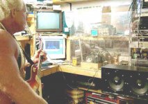
Testing some tube on the curve tracer.
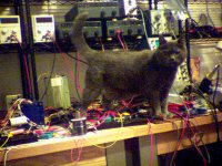
The cat checking out my circuitry for errors.
Powered up, without the cat, she knew better.
Fun with the hammer.
Time out, kayaking with the local natives.
Hammer in the morning....
The cat checking out my circuitry for errors.
Powered up, without the cat, she knew better.
Fun with the hammer.
Time out, kayaking with the local natives.
Hammer in the morning....
Attachments


Last edited:
Fun with the hammer.
Some of your tubes suffered "death by hammer." Some of mine get "death by power supply" before it's "Hammer Time."......
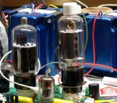
In one of my clip lead experiments I connected a pair of well used Chinese 6L6GC's into a Tubelab TSE amp and proceeded to find their limits. The tubes were pulled out of a Fender Bandmaster when its owner wanted it retubed. This was part of the testing that led to the development of the SSE amp design, so it was at least 10 years ago. I still have these tubes, and they still work, but usually only see duty for extreme testing and experiments where the outcome is uncertain. Pics #1 and #2
Take a SSE board (cathode biased SE amp), wire is as a fixed bias amp, and stuff in some sweep tubes. There was a feeding frenzy on tubes about 9 years ago when AES started clearing out all of their NOS tubes. Other vendors also got into the frenzy and I wound up with about 100 of these guys for an average cost of about 80 cents each......so the ugliest pair of supposedly NOS tubes got "tested." Pic #3 I think I squeezed over 20 watts in SE during this test. You could read by the light coming from the tubes. Some experiments seen here:
http://www.diyaudio.com/forums/tubes-valves/128533-tube-sale-aes.html?highlight=Tube+sale+AES
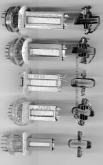
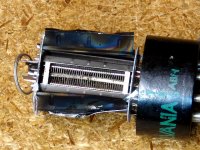
I ran several types of tubes through the "modified SSE" to find out what is useful for SE, and what is not. Here is a pair of 6CB5's. Pic #4 Only the tube on the right is active since only one channel was modified with the "adapter socket." Note the black chassis mount octal socket sitting on top of the white PCB socket. Note the "pimp my ride" metallic blue color of the Edcor OPT's. All Edcor's came in this color for their first year of direct to the DIY market sales. The response was mostly negative, so the switched to the mild blue that they use today.
I rewired the adapter to test some WE367A's that I found. I actually wired up an adapter in the second channel so I could listen to these tubes. They sounded nice, but I decided to sell them on Ebay to pay for more experiments.
Pic #5.
I had bought a sealed bulk pack box of 100 NOS Sylvania 6V6GT's from a NASA auction at cape Canaveral about 20 years ago. Upon opening the box I found that several of the tubes had gone to air and several more were losing their getters. I took the box home, tested all the tubes in a tube tester and tossed all the bad ones (a lot, maybe 30%), then put the box on a shelf in my closet.
A few years later I opened the box to find that many more had leaked. I again tossed the white ones and decided to test some that were silver, but fading in an SSE. Most had high distortion, so I went through the box and kept only the tubes that made reasonable THD. There were about 30 "good" tubes. I decided to test some of the tubes with high distortion in a more extreme manner, AKA death by power supply!
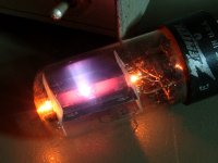
Tube #1 had minimal getter left, and there was obvious blue (gas) glow from inside the plate area. I ran it at 400 volts, above the spec, but good tubes survive this and draw about 35 mA in a SSE configured for a 6V6. This one drew about 50 mA and it started climbing. Pic #6
After an hour it looked like this and drew over 100 mA and was rising rapidly, so I killed the power and tossed the tube. Pic #7
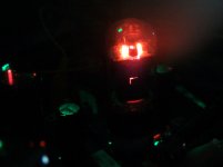
I tested several more with similar results until I found this one. It immediately sucked over 100 mA (pic #8) and within a few seconds a tube arc erupted at the top of the tube which caused the cathode bypass cap to explode. Pic #9
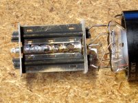
I arranged a meeting between Mr. Tube, and Maxwell's Silver Hammer! Pic # 10
Note the fried grid wires, bent cathode, and blackened plate.
I have since found more bad 6V6GT's in that box, and suspecting that they will all eventually die, I decided to take a pair of tubes that worked good last time I opened the box and subject them to some extreme, but not lethal (to a normal tube) testing. I put a pair in a P-P breadboard that I'm working on and cranked them......40 watts RMS at 2% distortion on 450 volts plate and 275 screen isn't bad for a 6V6GT and there was no glow or ill effects from about 15 minutes of testing. What's up with this box of tubes? I don't know.
Attachments
-
 6V6.jpg162.8 KB · Views: 100
 -
 Tube_2DEAD.jpg205.9 KB · Views: 81
 -
 Tube_2D.jpg169.3 KB · Views: 85
 -
 Tube_1C_b.jpg73 KB · Views: 95
 -
 Tube_1A.jpg279.8 KB · Views: 89
 -
 WE367A.jpg376 KB · Views: 86
 -
 6CB5_SYL_RCA.jpg255.8 KB · Views: 92
 -
 6BQ6GA.jpg228.4 KB · Views: 99
 -
 6L6_maxed.jpg137.7 KB · Views: 90
 -
 Chinese_6L6GC.jpg302.7 KB · Views: 112
Can you build a tube amp with cheap Radio Shack clip leads? Most people will tell you that you can't, you will either make an oscillator or a box full of hum. That didn't stop me from taking a working SSE board minus the tubes, a turret board with two novar sockets in it, and a box full of clip leads and building a "spud" amp.
The idea was simple use the SSE design, but substitute the triode section of a 6LR8 for the 12AT7 input stage in the SSE, and substitute the pentode section of the 6LR8 for the output tube in the SSE. Add a variable bench power supply to find out how much voltage it will eat, stir well and crank it up.
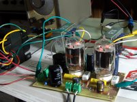
Pic #1 shows a "furball" of clip leads connecting the pair of 6LR8's into the SSE in place of the original 3 tubes.
Pic #2 shows the entire setup operational. It really worked the first time I flipped the switch. Don't try this with high Gm tubes though, you will create a great TV jammer......experience speaks!
OK, it works....now what? Call up the Eagle and make a PC board. Note, Eagle has recently been acquired by Autodesk, and their new pricing structure requires me to find an alternative. They want over $500 per year to lease the version needed to make SSE sized PC boards. That's beyond Tubelab's budget. Pic #3
Now that I have an amp....it's time to see what it will do. Pic #4
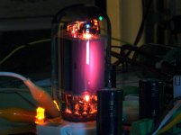
I found a 21LR6 with a crack running up the side of the glass. Pic #5
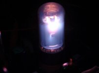
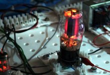
I wonder how much abuse I can feed this tube before it shatters? The 'LR6 is rated for a maximum plate voltage of 400 volts and max screen voltage is 300, so I tie the two together and start at 400 volts. No fun here it doesn't even glow. Ditto 450 volts, so I crank it to 500 volts. There it a faint glow and the amp is cranking out over 5 watts in triode mode. Pic #6
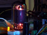
Worse case dissipation in a class A amp is no signal, so I turn off the audio generator. Now its glowing, but it just keeps on working. Plate dissipation is 36 watts. Pic #7
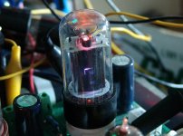
Note how the plate glow is not even, some of the plate is dark while some of it is red hot. This is common, but reveals that the tube has a minor alignment problem so that the plate current is not evenly distributed across the tube.
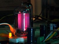
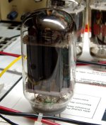
I found a Sylvania 21LR6 that glows evenly. The entire plate structure is roughly the same color. This shows even current distribution across the tube, and is rather rare. This is at 40 watts of dissipation. Pic #8
The idea was simple use the SSE design, but substitute the triode section of a 6LR8 for the 12AT7 input stage in the SSE, and substitute the pentode section of the 6LR8 for the output tube in the SSE. Add a variable bench power supply to find out how much voltage it will eat, stir well and crank it up.
Pic #1 shows a "furball" of clip leads connecting the pair of 6LR8's into the SSE in place of the original 3 tubes.
Pic #2 shows the entire setup operational. It really worked the first time I flipped the switch. Don't try this with high Gm tubes though, you will create a great TV jammer......experience speaks!
OK, it works....now what? Call up the Eagle and make a PC board. Note, Eagle has recently been acquired by Autodesk, and their new pricing structure requires me to find an alternative. They want over $500 per year to lease the version needed to make SSE sized PC boards. That's beyond Tubelab's budget. Pic #3
Now that I have an amp....it's time to see what it will do. Pic #4
I found a 21LR6 with a crack running up the side of the glass. Pic #5
I wonder how much abuse I can feed this tube before it shatters? The 'LR6 is rated for a maximum plate voltage of 400 volts and max screen voltage is 300, so I tie the two together and start at 400 volts. No fun here it doesn't even glow. Ditto 450 volts, so I crank it to 500 volts. There it a faint glow and the amp is cranking out over 5 watts in triode mode. Pic #6
Worse case dissipation in a class A amp is no signal, so I turn off the audio generator. Now its glowing, but it just keeps on working. Plate dissipation is 36 watts. Pic #7
Note how the plate glow is not even, some of the plate is dark while some of it is red hot. This is common, but reveals that the tube has a minor alignment problem so that the plate current is not evenly distributed across the tube.
I found a Sylvania 21LR6 that glows evenly. The entire plate structure is roughly the same color. This shows even current distribution across the tube, and is rather rare. This is at 40 watts of dissipation. Pic #8
Attachments

Although not an experiment, and more of a 5 year project, this yielded a few useful pictures.
I got a phone call from a friend about 10 years ago. He said that he had bought a lot of surplus that was found in a building that was being demolished. Apparently abandoned for at least 10 years, the building had its windows smashed out and had flooded several times. The demo team halted operations because "hazmat" had been found. The "hazmat" turned out to be mercury vapor tubes, some of which were broken.
He said that I could have "all the tubes for free" if I came and helped him load it all, move it, and unload it. We were talking about 10,000 sq feet of JUNK, and it was a 200 mile drive for me.
It took me several trips with rented trucks but I filled 4,000 cubic feet of warehouse space with tubes, mostly unboxed, unsorted tubes thrown randomly into cardboard boxes. The rotten boxes were tossed into a dumpster on site, and I had brought about 25 X 2 by 2 foot cardboard boxes (8 cu ft each) which wasn't enough. My estimate, based on weight and number of boxes, was 100,000 tubes after the obvious broken stuff was trashed, but before sorting.
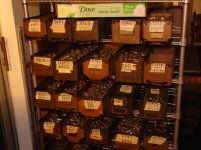
I then started the 5 year long project to sort all the tubes and sell, give away, or trash the stuff I didn't want.
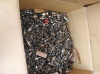
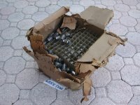
There were about 50 boxes like this, random loose tubes in mostly usable condition. So far they have been about 80% good. Pic #1
There were NOS tubes too. The rats had eaten much of the packaging, and water had turned many of the tube's pins green, some so bad they broke off when touched. Pic #2
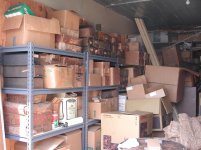
One corner of one (of three) storage bay. Pic #3
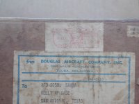
There were unopened boxes in relatively untouched shape from a long time ago. This one is from 1937 pic #4
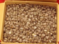
This box weighed in at about 60 pounds, all little tubes, mostly 6AL5's 6AK5's and 6AS6's. About 40% of them were trash (broken pins, broken glass, or corrosion). Pic #5
I set up racks to sort them in, and worked outside during good weather. Some boxes were full of rat or bird poop, bugs and roaches. Pic #6
After sorting I had several hundred 6AG5's. What are the odds of finding one with the ultra rare spare heater option.........what are the odds of finding TWO!
Pic #7
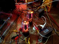
I was going through a box of random unboxed tubes when I discovered a 6AX4 damper rectifier. It had a hole burned through the plate. I stuffed it into the tube tester which said it was good. Not wanting to use it for anything useful, I decided to subject it to some "testing." I connected it to a pair of power supplies and ran a curve. The tube did indeed meet the V/I specs mentioned in the data sheet, and was therefore "good." What happens when we exceed the specs a bit....Pic#8
Exceed the specs a LOT! It arced and sparked for about 5 minutes. Pic #9
What's left.... Pic #10
I got a phone call from a friend about 10 years ago. He said that he had bought a lot of surplus that was found in a building that was being demolished. Apparently abandoned for at least 10 years, the building had its windows smashed out and had flooded several times. The demo team halted operations because "hazmat" had been found. The "hazmat" turned out to be mercury vapor tubes, some of which were broken.
He said that I could have "all the tubes for free" if I came and helped him load it all, move it, and unload it. We were talking about 10,000 sq feet of JUNK, and it was a 200 mile drive for me.
It took me several trips with rented trucks but I filled 4,000 cubic feet of warehouse space with tubes, mostly unboxed, unsorted tubes thrown randomly into cardboard boxes. The rotten boxes were tossed into a dumpster on site, and I had brought about 25 X 2 by 2 foot cardboard boxes (8 cu ft each) which wasn't enough. My estimate, based on weight and number of boxes, was 100,000 tubes after the obvious broken stuff was trashed, but before sorting.
I then started the 5 year long project to sort all the tubes and sell, give away, or trash the stuff I didn't want.
There were about 50 boxes like this, random loose tubes in mostly usable condition. So far they have been about 80% good. Pic #1
There were NOS tubes too. The rats had eaten much of the packaging, and water had turned many of the tube's pins green, some so bad they broke off when touched. Pic #2
One corner of one (of three) storage bay. Pic #3
There were unopened boxes in relatively untouched shape from a long time ago. This one is from 1937 pic #4
This box weighed in at about 60 pounds, all little tubes, mostly 6AL5's 6AK5's and 6AS6's. About 40% of them were trash (broken pins, broken glass, or corrosion). Pic #5
I set up racks to sort them in, and worked outside during good weather. Some boxes were full of rat or bird poop, bugs and roaches. Pic #6
After sorting I had several hundred 6AG5's. What are the odds of finding one with the ultra rare spare heater option.........what are the odds of finding TWO!
Pic #7
I was going through a box of random unboxed tubes when I discovered a 6AX4 damper rectifier. It had a hole burned through the plate. I stuffed it into the tube tester which said it was good. Not wanting to use it for anything useful, I decided to subject it to some "testing." I connected it to a pair of power supplies and ran a curve. The tube did indeed meet the V/I specs mentioned in the data sheet, and was therefore "good." What happens when we exceed the specs a bit....Pic#8
Exceed the specs a LOT! It arced and sparked for about 5 minutes. Pic #9
What's left.... Pic #10
Attachments
-
 DSCN2507.jpg327.5 KB · Views: 123
 -
 DSCN2377.JPG671.8 KB · Views: 105
 -
 DSCN2512.jpg324.6 KB · Views: 103
 -
 DSCN2370.JPG682 KB · Views: 115
 -
 Box_o_tubes.jpg195.8 KB · Views: 122
 -
 DSC00051.jpg746.7 KB · Views: 117
 -
 two_of_them.jpg164.6 KB · Views: 109
 -
 BluRay.jpg103.5 KB · Views: 103
 -
 Plasma.jpg101.2 KB · Views: 100
 -
 Autopsy.jpg162.8 KB · Views: 108
QRP?
Hamspeak for 'query - reduce power'. They use 1W or so transmitter power in QRP mode.
Fully balanced power amp: 6N1P 6N6P and G-807.
First test with normal output transformer, second test with toroid output transformer.
Fully balanced preamplifier: 6H8C (or 6SN7) and 6H13C.
Danilo
First test with normal output transformer, second test with toroid output transformer.
Fully balanced preamplifier: 6H8C (or 6SN7) and 6H13C.
Danilo
Attachments

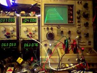
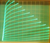
Upgrading the grid voltage step range on the TEK 576 Curve Tracer.
So it can do up to 168 V for grid 2 stepping. And 15 stepped curves now.
1) new step amplifier circuit on the heatsink
2) new Voltage boost power supply for the step amplifier (bottom, right)
3) example grid 2 curve trace for 6HJ5 Sweep tube, 8 Volt steps on grid 2, 50 mA/div Vert., 50V/div Horiz.
So it can do up to 168 V for grid 2 stepping. And 15 stepped curves now.
1) new step amplifier circuit on the heatsink
2) new Voltage boost power supply for the step amplifier (bottom, right)
3) example grid 2 curve trace for 6HJ5 Sweep tube, 8 Volt steps on grid 2, 50 mA/div Vert., 50V/div Horiz.
Attachments

- Status
- Not open for further replies.
- Home
- Amplifiers
- Tubes / Valves
- Pics of your random experiments!