Well, some consider greed a deadly sin. I was merely aiming at more noise suppression at lower frequencies... Subjectively, larger capacitors there produce fuller and thicker soundimage, but it depends on capacitor brand as well!
The main objective difference with very large Vref filtering capacitance is further 1/F (below 10HZ and near DC) noise suppression rather nice to digital clocks and chips but not that interesting in analog audio preamps. Fuller sound can sometimes be side-effect of larger also slower. Most here from what I remember ultimately preferred film capacitors when the noise was passable with small filtering like 10uF in line and headphone stages where the gain is low. But not all.
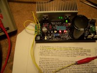
Thanks again to Salas for the wonderful schematic and to selfy for making DIY small compact PCBs. Here are some of my builds, configured to 5V at 600mA to power up the digital power supplies of a XMOS USB board.
The trimmer potentiometer to be replaced later with a fixed value resistor.
Two boards
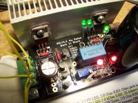
I bought the heatsink from TME. It is drilled using a standard drill press, the threads are milled with a tap. The aluminum alloy is very hard of this one.
Non magnetic, brass crews are used.
Here I soldered the rest of the components.
Here's also I third one I made today configured at 5V 1A to power up my SSD drive. It dissipates quite of heat. 😀
Best regards! 🙂
An externally hosted image should be here but it was not working when we last tested it.
The trimmer potentiometer to be replaced later with a fixed value resistor.
An externally hosted image should be here but it was not working when we last tested it.
Two boards
An externally hosted image should be here but it was not working when we last tested it.
I bought the heatsink from TME. It is drilled using a standard drill press, the threads are milled with a tap. The aluminum alloy is very hard of this one.
An externally hosted image should be here but it was not working when we last tested it.
Non magnetic, brass crews are used.
An externally hosted image should be here but it was not working when we last tested it.
An externally hosted image should be here but it was not working when we last tested it.
Here I soldered the rest of the components.
An externally hosted image should be here but it was not working when we last tested it.
An externally hosted image should be here but it was not working when we last tested it.
Here's also I third one I made today configured at 5V 1A to power up my SSD drive. It dissipates quite of heat. 😀
An externally hosted image should be here but it was not working when we last tested it.
Best regards! 🙂
Last edited:
The trimmer potentiometer to be replaced later with a fixed value resistor.
I use 500mW Vishay zener diodes or a combination of zener and LED for Vref. They sound better than the trimmer, at least to me. A good quality fixed-value resistor is worth experimenting as well 😉
I use 4V3 zener for 5V. I buy a batch of 20 or 50 and pick/match to my specific needs.
You did a great job with the finished regulators. Heatsinks look huge 😎
Hello.
I need to build a couple of BIB's for 3,3v (bjt ?) and I'm wondering if there is a fairly up to date BOM for that ? 😱
I need to build a couple of BIB's for 3,3v (bjt ?) and I'm wondering if there is a fairly up to date BOM for that ? 😱
To rephrase the question. Is the manual "Salas SSLV1.1 BIB boards guide (DocRev2)" from 2011 still up to date ?
There is nothing about the "R6 mod" there and I can't find it descibed here either, just to many pages to go through.
There is nothing about the "R6 mod" there and I can't find it descibed here either, just to many pages to go through.
Yes its still the correct reference doc for the 1.1 Bib. "R6 mod" is included as standard in the 1.1 design.
Yes its still the correct reference doc for the 1.1 Bib. "R6 mod" is included as standard in the 1.1 design.
Ok, thanks. No wonder I didn't find it then 😱
Hey all,
I am building a DAC and i can't decide which PSU to choose of about 7.5K posts written!!
DAC needs 2x 3V3. One for digital and one for analog
A 5V PSU is needed for the USB decoder and 2x 12or15V for the I/V converter
There are 3 different schemes i have read about
1.Reflector-D
2.SSLV1.1 BIB
3.The SSLV drawn by QuangHao For DAC End 2
Can you guide me to make the right decicion, which PSU for each output?
Reflector-D for digital
SSLV1.1 for analog
So you'll need 2x Reflector-D and 3x SSLV1.1
Thanks
Which SSLV of the 3 types below do you mean?
A)V1.1, B)V1.1 BiB, C)V1.2r
Are there these pcbs on sale or i have to design them?
Salas 24V BiB problem
Hi,
I built up the BiB positive reg SSLV v1.1 pcb from TeaBag.
For Q2 used lowest measured Vidss of (3.4) 2sk117 as supplied from TB.
For Q3 used medium measured Vidss of (4.27) 2sk117 .
For Q3 used highest measured Vidss of (5.18) 2sk117 .
--as per Appendix 5, suggested fet placement.
Appendix 1 c. 10V-25V Mosfet reg. indicates 2 1vpv LED + 1k8R for R3 + 5k trimmer, jumper other parts.
Here's what I get twiddling the 5k pot.
Lo 12v9, Hi 14v5, with Vac=27v15, Vdc35v4 (after diodes).
What I require is +25Vdc for a Pass BA-3 preamp board.
Thanks in advance for direction. 🙂
ICHI aka Joe
Try a higher R303 value first so we see how it reacts to it
Thank you for the response 🙂
I added in the following resistors at the jumpered zener position leaving the 1k8R in place...
2k44R gave max out voltage 14v5
5k0R --------------------- 14v6
100k0R ----------------------- 14v7
1m0R ----------------------- 14v7 red leds very dim with this one
So it does not add voltage. That makes me think maybe there is a problem with load current vs CCS current available. Do you use a dummy load, and what is its value?
So it does not add voltage. That makes me think maybe there is a problem with load current vs CCS current available. Do you use a dummy load, and what is its value?
Load with 100 ohms, measures 150.25mA at 14v533,
1v276 drop across 8r2 (R1 current Adjust resistor) = 155mA
Load with 50 ohms, ------------154.12mA
Heat sink is mildly warm, no components feel hot. 😕
Transformer output is 27v15acV
voltage past the diode bridge is 35dcV
The heavy dummy load eats up all your CCS early. In other words the reg enters constant current protection mode (just like a lab PSU) when the CCS preset is met. A dummy must be calculated as a representation of your goal load. Say 500 Ohm for a 25V rail 50mA bias load.
I suggest you try again with the reg in original R303 state and a 500 Ohm dummy.
I suggest you try again with the reg in original R303 state and a 500 Ohm dummy.
The heavy dummy load eats up all your CCS early. In other words the reg enters constant current protection mode (just like a lab PSU) when the CCS preset is met. A dummy must be calculated as a representation of your goal load. Say 500 Ohm for a 25V rail 50mA bias load.
I suggest you try again with the reg in original R303 state and a 500 Ohm dummy.
Now tried a 226R load, which with 24v should give a 106mA load to reg.
The result was I got to set voltage out to 24v 🙂 but current measured 91.86mA ?
So, you nailed it! 😉 I was drawing too much current demand.
Don't quite understand why I'm only getting 151mA through R1 (8R4)
when instructions table shows 240mA for an R1 of 8R2 ? I would
guess it has to do with variances of the active devices ? But, that's
beyond my understanding.
What the Pass BA-3 pre-amp requires is a +- 24V supply with 53 mA
per channel, so 106mA total.
Cheers

Now tried a 226R load, which with 24v should give a 106mA load to reg.
The result was I got to set voltage out to 24v 🙂 but current measured 91.86mA ?
Maybe due to this Burden Voltage - NI Digital Multimeters Help - National Instruments
Don't quite understand why I'm only getting 151mA through R1 (8R4)
when instructions table shows 240mA for an R1 of 8R2 ? I would
guess it has to do with variances of the active devices ? But, that's
beyond my understanding.
What the Pass BA-3 pre-amp requires is a +- 24V supply with 53 mA
per channel, so 106mA total.
Cheers
Is it the calc sheet that pointed 240mA? Measure your green leds Vf in circuit and if its significantly lower than assumed in the calc it can be due to surely lower current provided to them in circuit by a source resistor degenerated JFET than nominal which is stated for high enough current.
Think of 2-3mA and look up their Vf curve in datasheet to see if its near what you can measure across each. Correct to your original goal with a smaller value CCS set resistor or by paralleling one extra to reach the proper value together. Some spare current is good to have.
- Status
- Not open for further replies.
- Home
- Amplifiers
- Power Supplies
- The simplistic Salas low voltage shunt regulator