Either change the JFET to less IDSS as its the most ambient temperature sensitive for producing more current with rising Celsius or simply replace the green led with a healthy Vf red one so to lose around 0.2V
If it was tempco causing output voltage drift, then it would get to the final voltage in a couple of hours.
But he is referring to drift over months/years.
But he is referring to drift over months/years.
Either change the JFET to less IDSS as its the most ambient temperature sensitive for producing more current with rising Celsius or simply replace the green led with a healthy Vf red one so to lose around 0.2V
Thank you.
I have spare yellow Kingbright WP2773 LED which theoretically gives 0.1V drop (compering green LED). So I applied it and currently have 3.28Vout (close to my target).
I'll be watching in the coming months possible Vout change (just for curiosity).🙂
Hello, i need some help.
i have four boards for my akm dac.
i need 2x 5v and 2x 3.3v
i want to buy the transformers. i found r-cores 30va 2x9v.
what is the best performance?
should i buy 4 transformers??? one for each voltage or buy 2 transformers (one for 2 x 3.3 and one for 2x 5v.)?
this maybe a silly question but i´m not from electronics. help appreciated.
regards
You may use just two transformers taking advantage of each secondary pair of wires individually provided you are not needing to set for unusually high currents.
You may use just two transformers taking advantage of each secondary pair of wires individually provided you are not needing to set for unusually high currents.
thank you very much 🙂
Hi, I found some 2SK117GR that the sellers claim to be NOS. Bought a few and the IDSS all test between 2.7~5.5mA with 9V battery. Slightly lower if I lower the voltage with a diode. Too bad I don't have a tracer. Is there any way to identify this by look? Thanks.
Attachments
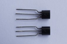
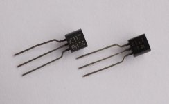
The right one in the second photo has legit characters print
Thanks. 🙂
Now measure the Vpinchoff.
Then using Idss and Vpinchoff you can calculate the gm as a third check on genuine GR grade.
Then using Idss and Vpinchoff you can calculate the gm as a third check on genuine GR grade.
Now measure the Vpinchoff.
Then using Idss and Vpinchoff you can calculate the gm as a third check on genuine GR grade.
Hi, is it the Vgs(OFF), the gate-source cut-off voltage, as in the 117 data sheet? Thanks.
yes, Borbely shows how to measure and to calculate.
Vpinchoff cannot be read off the graph in the datasheet.
You need ~1M to 10M in the source leg to reduce the source and drain current to ~1uA and then you measure the Vgs for that condition. It is way off the side of the graph.
Vpinchoff cannot be read off the graph in the datasheet.
You need ~1M to 10M in the source leg to reduce the source and drain current to ~1uA and then you measure the Vgs for that condition. It is way off the side of the graph.
yes, Borbely shows how to measure and to calculate.
Vpinchoff cannot be read off the graph in the datasheet.
You need ~1M to 10M in the source leg to reduce the source and drain current to ~1uA and then you measure the Vgs for that condition. It is way off the side of the graph.
Thanks for the detailed instructions. 🙂
yes, Borbely shows how to measure and to calculate.
Vpinchoff cannot be read off the graph in the datasheet.
You need ~1M to 10M in the source leg to reduce the source and drain current to ~1uA and then you measure the Vgs for that condition. It is way off the side of the graph.
Also got Mr. Borbely's article on jfet. What a wonderful read! Thanks again for sharing. 🙂
D
Deleted member 548388
This is my final Reflektor-D.
I used 1R2 2W for R1 and 47R for RR. Together with a custom made trafo by toroidy.pl it delivers exactly 5.01V DC. Honestly, I didn't measure ripple jet, but I like the result a lot! 🙂
An externally hosted image should be here but it was not working when we last tested it.
I used 1R2 2W for R1 and 47R for RR. Together with a custom made trafo by toroidy.pl it delivers exactly 5.01V DC. Honestly, I didn't measure ripple jet, but I like the result a lot! 🙂
Hello again, i need some technical help for choosing the correct CSS and the respective R1 value.
The objective is the one refector for left and other for right channel on akm4497
datasheet it says:
FOR VREFHL/R=VDDL/R=5.0V
VDDL/R(total) typical=64 max=96 ma
VREFHL/R typical=1 max=1.5 ma
when they say total for VDDL/R means for both channels???
what is the correct value for R1??? 2, 2.5 or even more?? from what i read in the thread if the power consumption is to low for an hight CSS choose it will produce a lot of heat unnecessary...
as for for choosing RR i have to measure the IDSS J1? correct??
in my kit i have two J1 = 2SK117GR so one if for the board and the other if for the r6 mod???
thanks
ICCS=0.6V/Rset. 2.5R should provide plenty of mA (about 240mA) for the consumption you quote and keeping a good spare without overheating. Rich spare current keeps the rail distortion lower. They should mean L+R total when they state L/R total. If you want to verify the chip's draw per channel or the total you can measure it with a DMM on mA in series with it and a 5V source. Or 1 Ohm resistor between and the DMM on DCV across the resistor to see I=V/R.
Yes, you understood correctly on the JFETs.
Yes, you understood correctly on the JFETs.
D
Deleted member 548388
It's supposed to supply this module: I2SoverUSB - I2S over USB AudioLooking nice. For what design is it to supply for?
My plan is to build a headamp consisting of the I2SoverUSB Module, a dam1021-12 module, an output stage, a Wire BAL-BAL module and the respective PSUs, of course.
- Home
- Amplifiers
- Power Supplies
- Reflektor-D builds