Sounds like there's certain fluctuation in this hum, normally present is some EMF is catched by the input.
I'm just not sure if you've checked all the obvious "points of failure", like the interconnect itself - if by some reason its ground wire (screen?) is damaged, you will habe this kind of hum for sure.
Does it happen to this amplifier only, or some other ones also demonstrate some similar behavior?
Is it possible that this hum present at the receiver's output all the time?
Just trying to localize the possible source of the issue.
Its not there at the AV receiver output.Sounds like there's certain fluctuation in this hum, normally present is some EMF is catched by the input.
I'm just not sure if you've checked all the obvious "points of failure", like the interconnect itself - if by some reason its ground wire (screen?) is damaged, you will habe this kind of hum for sure.
Does it happen to this amplifier only, or some other ones also demonstrate some similar behavior?
Is it possible that this hum present at the receiver's output all the time?
Just trying to localize the possible source of the issue.
When I use mobile as source with 3.5mm stereo jack and connect using RCA * with the same interconnect * i get absolutely zero hum or noise out of this. This happened earlier as well.
I dont have RF filter at the input but I see hum is major problem here. If its input noise above 100Khz as the RF harmonics would be fine with RF filter.
Tell me one thing do we need to have isolators at the base of the transformer? Im using Rcore transformers One small for IPS+VAS and one large for the OPS.
I tried this even with a single E&I Transformer but the problem is same.
Last edited:
If your transformer has a small voltage difference between the two secondery winding, and you are using a single rectifier bridge, you will hear a hum that cannot be cured. in this case use two bridges, one for each tap...
Last edited:
Something like this?If your transformer has a small voltage difference between the two secondery winding, and you are using a single rectifier bridge, you will hear a hum that cannot be cured. in this case use two bridges, one for each tap...
A instead of B?
Attachments
If your transformer has a small voltage difference between the two secondery winding, and you are using a single rectifier bridge, you will hear a hum that cannot be cured. in this case use two bridges, one for each tap...
In this case the hum would present even if the amplifier is not connected to the signal source. But this is not the case. It's only there as soon as it's connected to the receiver. There must be an external ground loop somewhere between the amp and the receiver...
It might sound difficult, but I would disconnect everything from the receiver to check if hum is still there while connected only to the amp. If then no hum is present I would start adding the input sources to identify the source of hum
Sent from my iPhone using Tapatalk
Sent from my iPhone using Tapatalk
rhythmsandy
Please make a nice picture of Yours setup, it would be easier to diagnose the hum problems. I am allways using single bridge rectifiler with hum free resaults.
Make a separate star point for signal GND return.
Regards
Please make a nice picture of Yours setup, it would be easier to diagnose the hum problems. I am allways using single bridge rectifiler with hum free resaults.
Make a separate star point for signal GND return.
Regards
Even i feel the same as when connected to the mobile 3.5mm jack the hum or noise absolutely not there.In this case the hum would present even if the amplifier is not connected to the signal source. But this is not the case. It's only there as soon as it's connected to the receiver. There must be an external ground loop somewhere between the amp and the receiver...
a 3.5mm trs has a common return for the two signal feeds to tip and ring.
Because it has that common return there cannot be a loop in the TWO returns that are not there.
Using two interconnects where the two returns meet up at the source is what creates the loop in the signal return. Interference impinging on that loops adds to the signal voltage and you hear that interference at the speaker.
But you would not follow my instructions to help find where the interference was getting in.
Hence the questions about the hum:
- no inputs connected to the receiver;
- one channel is connected to the receiver;
- two channels are connected to the receiver.
test 1 complete.
What about tests 2 and 3?
__________________
try connecting a long interconnect to one input and short the far end with a zero ohms link.
Keep the shorting plug on the other input.
Is there hum?
Measure it and post the result here.
Now swap the shorting plug and the long interconnect, measure and report.
measure the interference signal.
Last edited:
a 3.5mm trs has a common return for the two signal feeds to tip and ring.
Because it has that common return there cannot be a loop in the TWO returns that are not there.
Unless he actually has a TRS jack as an input to his amplifier, he will be using a TRS/RCA adapter cord which has two audio grounds which are normally connected together in the cable, so yes it can contribute to a ground loop.
will do it soon my cro is on the way.a 3.5mm trs has a common return for the two signal feeds to tip and ring.
Because it has that common return there cannot be a loop in the TWO returns that are not there.
Using two interconnects where the two returns meet up at the source is what creates the loop in the signal return. Interference impinging on that loops adds to the signal voltage and you hear that interference at the speaker.
But you would not follow my instructions to help find where the interference was getting in.
you don't need a scope.
Just measure the Hum+ Noise at the amplifier output. A DMM set to 199.9mVac is good enough
a.) both inputs shorted.
b.) one input shorted one open
c.) one input shorted one with long interconnect.
d.) one input shorted and one long interconnect with the far end shorted.
repeat b, c and d for swapped inputs.
e.) two long interconnects both open.
f.) two long interconnects both shorted.
g.) two long interconnects both shorted, but this time with the barrels shorted together.
Last edited:
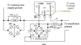
Andrew will do the above list of tests but just to know how about using this one in the connecting to the power ground.
I know that the rightside of the ckt is to block the DC which might enter into the trafo.
But i have a question regarding that how many amps does the bridge to be rated?
I know that the rightside of the ckt is to block the DC which might enter into the trafo.
But i have a question regarding that how many amps does the bridge to be rated?
Attachments
Last edited:
There are two bridge rectifiers.
The left side Bridge:
One is a Safety and in the Disconnecting Network. This must be capable of passing Fault current that can approach and even exceed 1kA. I have used 25A and 35A in paralleled mode for this duty. The pic shows the diodes in series mode.
To date I am the only Member that has tested and reported on this Disconnecting Network. My version passed. This connects from Audio Zero Volts to Chassis.
The diagram posted has omitted the connection from PE to Chassis. You MUST connect PE to Chassis.
The right side bridge:
This one is the DC blocker to help reduce the DC current through the primary of the mains transformer. The rated current of the transformer would be a good guide to choosing a diode bridge for the DC blocker. I have used 3A diodes, but two in series in each direction so that they don't pass any significant current when the capacitor peak voltage is <1000mVpk
I don't like the polar capacitors with reverse voltage applied to them. I use back to back polar capacitors for this duty.
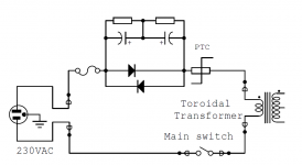
the mains fuse and switch go into the Live feed.
The DC blocker can go into either feed.
In my opinion the PTC should not be there at all.
An NTC could be used but it should be bypassed by a relay to lower the source impedance seen by the transformer.
Your single diodes will start passing at voltages around 400mVpk.
That would require enormous capacitors instead of just very big capacitors.
I use large banks of 3300uF 16V, or 4700uF 10V, to ensure low impedance at 50Hz.
The cap impedance determines the voltage across the caps and across the diodes.
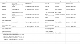
I have done as per you have said and here are the results of the test.
I have used the above earthing scheme with chassis ground and the PE is connected to transformer center tap / psu ground via a bridge and 100ohm+100nF combination as in the circuit diagram.
The last case is the strangest part im able to hear.
Even though there is an EMI filter Im able to hear that.
I have used the above earthing scheme with chassis ground and the PE is connected to transformer center tap / psu ground via a bridge and 100ohm+100nF combination as in the circuit diagram.
The last case is the strangest part im able to hear.
Even though there is an EMI filter Im able to hear that.
Attachments
Last edited:
you are showing Vdc for output offset.A DMM set to 199.9mVac is good enough
Where are the Vac measurements for Hum + Noise?
will do it again with Vac measurements but can you identify just by the hum being audible as mentioned in the table above that where the problem might be?you are showing Vdc for output offset.
Where are the Vac measurements for Hum + Noise?
- Status
- Not open for further replies.
- Home
- Amplifiers
- Solid State
- Kypton V2