From your descriptions, it seems very likely that the twin interconnects are creating a loop that is picking up interference and injecting that into the two inputs.
It is easily overcome by adopting HBRR+HBRL.
But let's see the measurements, they will tell you and us a lot more than your ears ever can.
It is easily overcome by adopting HBRR+HBRL.
But let's see the measurements, they will tell you and us a lot more than your ears ever can.
but what is HBRR+HBRL i never heard this term?😕From your descriptions, it seems very likely that the twin interconnects are creating a loop that is picking up interference and injecting that into the two inputs.
It is easily overcome by adopting HBRR+HBRL.
But let's see the measurements, they will tell you and us a lot more than your ears ever can.
Have you tried with a shorted R3?doesnt R3 comes under HBRR?what if i increase R3 to 47ohm or 100ohm?
Attachments
Last edited:
yes we have shorted and removed the 4148 diodes and still i find the same problem infact it has increased a bit after that change.
The problem is the internal grounding scheme.
Your table shows - the hum appears as soon as you connect input A to input B.
In other words - as soon as you connect input A ground to input B ground - you have an internal ground loop, resulting in hum in both channels.
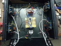
For investigating further, we need to see a detailed wiring diagram - not schematic diagram, but a picture of the amp case with all the modules, showing how and where they are inter-connected (as we mentioned some time earlier).
Your table shows - the hum appears as soon as you connect input A to input B.
In other words - as soon as you connect input A ground to input B ground - you have an internal ground loop, resulting in hum in both channels.
For investigating further, we need to see a detailed wiring diagram - not schematic diagram, but a picture of the amp case with all the modules, showing how and where they are inter-connected (as we mentioned some time earlier).
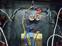
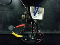
The twisted yellow blue and black are the wires from the psu to amplifier modules.
NTC is in series with mains phase.
I have a doubt regarding the speaker output negative terminal do we have to connect the speaker negative to the power ground directly? I have it right now on the amplifier output stage directly connected.
NTC is in series with mains phase.
I have a doubt regarding the speaker output negative terminal do we have to connect the speaker negative to the power ground directly? I have it right now on the amplifier output stage directly connected.
Last edited:
since the speaker output return is on the amp PCB, that is where the twisted pair to the speaker comes from.
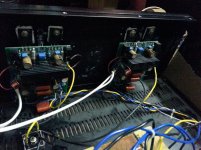
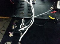
You pics show nothing as a twisted pair. You even have plaited triplet wires where they could be twisted triplets, (twisted yellow blue and black) are plaited. This increases the loop area.
Some of your wires are close coupled. These would be better twisted.
All the other single wires will each have a partner. All of these singletons should be paired up as Flow and Return and twisted together.
Where are the H+N measurements?
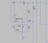
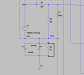
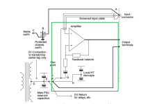
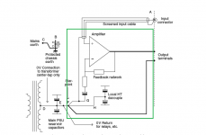
the green outline is the amplifier module.
The speaker output ground is on the amplifier pcb.
The input signal shouldn't connect to earth ground. The audio ground/return should through the lifted ground/disconnecting network on the input of the amplifier.
The input signal shouldn't connect to earth ground. The audio ground/return should through the lifted ground/disconnecting network on the input of the amplifier.
This is how its connected. I have not used shield even though there is. So does the shield to be connected to the signal ground?
Attachments
This is how its connected. I have not used shield even though there is. So does the shield to be connected to the signal ground?
The shield will act as an antenna if it's not connected to anything, so it needs to be connected to something. I have the best results connecting it to signal ground in my amps. The shield is only connected at one end to prevent a possible loop.
Last edited:
since the speaker output return is on the amp PCB, that is where the twisted pair to the speaker comes from.
You pics show nothing as a twisted pair. You even have plaited triplet wires where they could be twisted triplets, (twisted yellow blue and black) are plaited. This increases the loop area.
Some of your wires are close coupled. These would be better twisted.
All the other single wires will each have a partner. All of these singletons should be paired up as Flow and Return and twisted together.
Where are the H+N measurements?
ok will twist the wires than plaiting it. Can you tell me how to wire using shielded cable.
The shielded cable having two wires inside with one shield on the outside.
So lets consider
Wire 1: red as positive
Wire 2: white as negative
Shield: Do we need to connect this to negative?
shielded wire into the chassis wiring
At the amplifier signal input at the chasiss. Do we need to connect the shielded wire to the chassis and not connect to the signal negative
At the amplifier board input: The white wire which is actually assigned to negative do we need to connect this to shield? or leave the shield alone?

here is the shield wiring scheme please tell me how to use the shield.
Do we need to connect
A and B on one side C and D on other side?
Or leave B and connect D to E as in chassis earth?
Or leave B and connect at C D E to one point on chassis earth?
With all my builds I've had the best results connecting C to D and leaving B disconnected. This is a trial and error process. Some connect D to E with good results instead.
Last edited:
Connect the shield to the enclosure at both ends with a very low impedance tape/clamp.
At the PCB end if you have an adjacent Power Ground plane that is low impedance connected to the enclosure then the shield can connect to the power plane via a low impedance.
The shield attenuates the interference that impinges on the internal twisted pair.
The twisted pair MUST be maintained as the Flow and Return pair for the signal to pass and return to source.
I cannot recommend you attach the interference carrying shield to the signal return at the input socket. That just sounds wrong, to connect noise into the signal wiring !
I cannot recommend you attach the interference carrying shield to the signal return at the input socket. That just sounds wrong, to connect noise into the signal wiring !
It sounded right to you when you recommended I do this with my first Slewmaster amp. What has changed?
I just feel that the shield will anyway accumulate the stray signals which actually have to be away from the signal wiring. connecting the shileld to the chassis would eventually take out that unwanted induced signal to chasiss. Now my main concenrn is that how to solve that looping issue when two channel signals are connected together like valery said.It sounded right to you when you recommended I do this with my first Slewmaster amp. What has changed?
I will be taking the AC measurements by tomorrow. But in the mean time i will try the shield connecting to the metal part of the amp module pcb spacer and the other end at the input of the chassis will connect the signal ground to the chassis and also twist the three wires instead of plaiting it and post the results.
Do i need to change the speaker return to direclty to psu ground at the psu capacitors?
- Status
- Not open for further replies.
- Home
- Amplifiers
- Solid State
- Kypton V2