This is why I recommended a trial and error method of testing this. What I have found is chassis grounding does work, but when the amp is put into service some noise can enter the shield from the earth ground in the house (PC ATX power supply noise). This is actual building experience, not nose in a book experience. This will be different in different geographic locations because of differing grounding methods and wiring codes. Here in North America we run smaller gauge ground and mains wiring than in many other parts of the world. My Slewmaster with the Kypton-C input boards was especially sensitive to this.I just feel that the shield will anyway accumulate the stray signals which actually have to be away from the signal wiring. connecting the shileld to the chassis would eventually take out that unwanted induced signal to chasiss. ?
You are running a single power supply that shares a common main audio ground with all your amplifier channels. This makes it tough to eliminate ground loops. If you were to use separate bridges (I prefer dual bridges per channel) and supply banks for each amplifier channel and wired them as if each channel was a separate mono-block amplifier, the ground loop would be broken inside the amplifier. This also can improve stereo image/crosstalk dramatically.
Im using two trafo one for the driver stage and one for the OPS so eventually it becomes much complex and expensive for the power supply especially when using higher quality capacitors like Mundorf or Jensen and also massive space as well.This is why I recommended a trial and error method of testing this. What I have found is chassis grounding does work, but when the amp is put into service some noise can enter the shield from the earth ground in the house (PC ATX power supply noise). This is actual building experience, not nose in a book experience. This will be different in different geographic locations because of differing grounding methods and wiring codes. Here in North America we run smaller gauge ground and mains wiring than in many other parts of the world. My Slewmaster with the Kypton-C input boards was especially sensitive to this.
You are running a single power supply that shares a common main audio ground with all your amplifier channels. This makes it tough to eliminate ground loops. If you were to use separate bridges (I prefer dual bridges per channel) and supply banks for each amplifier channel and wired them as if each channel was a separate mono-block amplifier, the ground loop would be broken inside the amplifier. This also can improve stereo image/crosstalk dramatically.
What if i use a buffer or preamp with fixed gain like 2 will that solve the issue?
But yes shield wire im trying to fix it.
Please tell me how does using two bridges in the power supply will help in breaking the groundloop? If the result is definite then i dont mind getting that custom ones done.
I don't think dual bridges actually help with a ground loop. They allow you to isolate the two secondary windings of the transformer.
Hi Jeff,what do you think about dual caps bank?I don't think dual bridges actually help with a ground loop. They allow you to isolate the two secondary windings of the transformer.
All my past experience shows very good results.
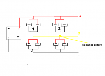
Power supply 0V and speaker return on second cap bank
Attachments
Last edited:
rhythmsandy
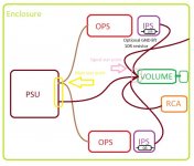
A I can see on the pic, You have one GND star point.
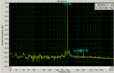
In my opinion better way is to use two star points (I am allways using this setup). Signal star point must be moved away from main PSU GND star point (to make sure no AC component is ''floating'' there). I am using single bridge rectifier on PSU and the ''humm'' component at FFT is very low.
I do not checked Yours PCB's but please make sure that signal GND have separate return (so the main GND connector is not connected to the NFB and input network).
Regards
A I can see on the pic, You have one GND star point.
In my opinion better way is to use two star points (I am allways using this setup). Signal star point must be moved away from main PSU GND star point (to make sure no AC component is ''floating'' there). I am using single bridge rectifier on PSU and the ''humm'' component at FFT is very low.
I do not checked Yours PCB's but please make sure that signal GND have separate return (so the main GND connector is not connected to the NFB and input network).
Regards
Attachments
Hi Jeff,what do you think about dual caps bank?
All my past experience shows very good results.
Power supply 0V and speaker return on second cap bank
Hi Thimios.
I haven't experimented with that yet but I can see how it might remove some ground noise from the input. This would be kind of like what Borys is suggesting but a more extreme version.
In other words what you are telling is to have a buffered stage/ preamp so that the signal ground of amplifier will get ground from the previous stage?rhythmsandy
A I can see on the pic, You have one GND star point.
In my opinion better way is to use two star points (I am allways using this setup). Signal star point must be moved away from main PSU GND star point (to make sure no AC component is ''floating'' there). I am using single bridge rectifier on PSU and the ''humm'' component at FFT is very low.
I do not checked Yours PCB's but please make sure that signal GND have separate return (so the main GND connector is not connected to the NFB and input network).
Regards
I don't recall any details. It appears there is something different between the two recommendations.It sounded right to you when you recommended I do this with my first Slewmaster amp. What has changed?
ok here we go..
I made the following changes
1. The acutal connection from PE to the PSU ground was not there by mistake it wasnt connected. Now its connected
2. The shield at the input of the chassis is connected there instead of connecting to the signal ground its connected to the chassis. Just to test
3. Used an 470nF X2 capacitor across the output of the EMI filter
4. Used an Low pass filter at the input of the amp board with 47ohm with 100nF resulting in 33KHz low pass.
Now the results as follows
When input of one channel is connected to the input of other channel no hum
when input is shorted no hum
when interconnect input is left without any connection no hum
when lift operates no hint of sound because of lift.
The upper frequency noise was gone when lowpass filter was used.
but one thing when we get very close to the speaker as low as 5cm i can hear very very faint hum hardly noticable.
but with long interconnects either shorted or open no hum atall. Infact its dead silent only thing is that when we get very close as close as 5cm to speaker i can hear faint hum. I have checked that is the signal cable passing over the power cable but no even if i take the signal cable closer to power cable there is no hum being induced or the induced hum is being supressed by the shield wire.
Overall im quite happy with whatever the result has shown up but yes its not the end i want to takeout that faint hum when getting too close to the speaker.
Thank you all Valery, thimios, AndrewT, Jwilhelm etc in helping me to solve the issue.
Like said now the challenging part is to identify the hum source for that super low hum.
I don't recall any details. It appears there is something different between the two recommendations.
Your convenient memory lapse isn't a huge surprise. This seems to be your normal response whenever someone calls you on your bull$hit.
I've confirmed my findings with someone with a more sound memory and who has more practical experience than all of us put together, and my connection of the shield to audio ground is correct.
I mean like this.
There are a lot of so called audio gurus with completely different opinions on connecting grounds this way, but most of them agree the grounds shouldn't connect directly between the capacitors like that due to the high current of charging and discharging the capacitors right there. I haven't tested this myself, but I can see some possible advantage to dumping the high current from the speaker returns somewhere other than where the audio ground connects though.
Randy Slone had some published disasters but I still think a lot of his theory is correct. His recommendation on connecting capacitors was to have a distinct path in and out of the capacitor for current flow. If the path is shared for charging and discharging current flow is doubled through the trace and it will emit AC noise at twice the input frequency. With the individual paths, current isn't doubled and it's DC so less noise is emitted. In my supplies I've been cheating and just using large planes for rails and ground but I try to keep with the in and out path for current. I'm slowly accumulating some actual audio grade test gear to go along with my automotive gear so I can hopefully begin actually testing this more thoroughly soon.
If you want to remind by giving a link I will look.Your convenient memory lapse isn't a huge surprise. This seems to be your normal response whenever someone calls you on your bull$hit.
I've confirmed my findings with someone with a more sound memory and who has more practical experience than all of us put together, and my connection of the shield to audio ground is correct.
rhythmsandy
According to post 90 you seem to have find a good solution to your hum problems. Could you please bring us a drawing like the one you brought in post 73 with all your last changings. For many of us a drawing is better than "hundreds words" or photos on how to find a good solutions to the hum problems with the Kypton V2 IPS.
Eivind S
rhythmsandy
Can you please provide a drawing of your solution. I am having the same problem with the Spooky IPS. When the ground wires of the two channels are connected (as when connected to a 3.5mm plug), I get the noise. The noise is barely audible, but it is there and it is definitely irritating.
Hari
Can you please provide a drawing of your solution. I am having the same problem with the Spooky IPS. When the ground wires of the two channels are connected (as when connected to a 3.5mm plug), I get the noise. The noise is barely audible, but it is there and it is definitely irritating.
Hari
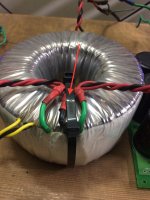
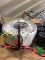
OK, problem solved. The cause of the noise was incorrect orientation of the transformer secondary wires. It sounds far fetched, but true. There is absolutely no noise now. Amp working perfectly now, have put it on endurance testing. See the photos below, the one on the left is the incorrect orientation.
Hari
Hari
Attachments
I have a strange issue with the Kypton v2 regarding while settingup the 5.5ma output from PD+ and ND- and actually since I was using at different voltages I had to use a pot to adjust this value for precision. The major problem is that when i set it to 5ma the value starts crawling up and goes over 10ma sometimes and eventually the OPS bias also increases accordingly or it takes almost one hour to stabilize it to a constant value.
I would like to know how do we get it rocksolid stable in may be 5 mins or almost realtime? why is this happening like im waiting for quite long for this value to get stablized.
I would like to know how do we get it rocksolid stable in may be 5 mins or almost realtime? why is this happening like im waiting for quite long for this value to get stablized.
rhythmsandy
According to post 90 you seem to have find a good solution to your hum problems. Could you please bring us a drawing like the one you brought in post 73 with all your last changings. For many of us a drawing is better than "hundreds words" or photos on how to find a good solutions to the hum problems with the Kypton V2 IPS.
Eivind S
use a bridge rectifier with a 100nF/630v cap connected to the center tap as in schematic. DCblock.gif gif by dkleitsch | Photobucket
it would help.
I have a strange issue with the Kypton v2 regarding while settingup the 5.5ma output from PD+ and ND- and actually since I was using at different voltages I had to use a pot to adjust this value for precision. The major problem is that when i set it to 5ma the value starts crawling up and goes over 10ma sometimes and eventually the OPS bias also increases accordingly or it takes almost one hour to stabilize it to a constant value.
I would like to know how do we get it rocksolid stable in may be 5 mins or almost realtime? why is this happening like im waiting for quite long for this value to get stablized.
Hi Rhythmsandy,
Can you please show the exact schematic you're using and specify the rail voltage.
Cheers,
Valery
Hi Rhythmsandy,
Can you please show the exact schematic you're using and specify the rail voltage.
Cheers,
Valery
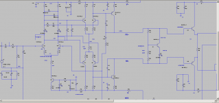
Here is the schematic and Im using 5 pairs of IRFP240/9240 at 70VDC
IPS Stage at +/-70VDC and OPS at +/-64VDC
Attachments
- Status
- Not open for further replies.
- Home
- Amplifiers
- Solid State
- Kypton V2