There is a huge(!!!) difference at pcbway for example:
100x100mm 2 layers (10 pieces): 10$
100x100mm 4 layers (10 pieces): 53$
Which layout editor software do you use?
100x100mm 2 layers (10 pieces): 10$
100x100mm 4 layers (10 pieces): 53$
Which layout editor software do you use?
Last edited:
Well, if you make a universal design maybe somebody else will be interested.
Order 20 pcs. 4 layer and sell the spare boards.
~ 5$ for one 4 layer board (53$ for 10 boards) you can't call it expensive. 🙂
Kicad
Order 20 pcs. 4 layer and sell the spare boards.
~ 5$ for one 4 layer board (53$ for 10 boards) you can't call it expensive. 🙂
Kicad
You may be right.... but 2 layers are for me OK at the moment...🙂
What do you think about the big Vref capacitors? Are they really necessary if the regulators are placed close to the DAC on the pcb?
What do you think about the big Vref capacitors? Are they really necessary if the regulators are placed close to the DAC on the pcb?
You may be right.... but 2 layers are for me OK at the moment...🙂
What do you think about the big Vref capacitors? Are they really necessary if the regulators are placed close to the DAC on the pcb?
The attachment is for AK4490. Also take a look at the notes on page 78 of AK4458 datasheets.
Attachments
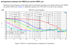
"Power lines of AVDD and VREFH1-4 should be distributed separately from LDO and etc. while keeping low impedance. If it is not possible, it is recommended to connect a LPF composed by a 10Ω resistor and a 220uF capacitor between VREFL1-4 and VREFH1-4."
I know this magic curve, but datasheet says that these are needed if the regulator is far away from the IC....
(and don't forget, the AK4490 evaluation board uses an add-in panel for the DAC chip...)
I know this magic curve, but datasheet says that these are needed if the regulator is far away from the IC....
(and don't forget, the AK4490 evaluation board uses an add-in panel for the DAC chip...)
Last edited:
The attachment is for AK4490. Also take a look at the notes on page 78 of AK4458 datasheets.
The AK4495 evaluation board manual shows not much benefit from bigger Vref capacitance so I think it is somewhat chip dependant, the THD for that chip goes down almost 10dB if it is used at less then -3dB below fullscale output though.
I've found something...🙂
http://www.akm.com/akm/en/file/ev-board-manual/AK4458VN.pdf
47uF II 10nF...
http://www.akm.com/akm/en/file/ev-board-manual/AK4458VN.pdf
47uF II 10nF...
Last edited:
In that form of course, but if I am using jumpers and not dip-switches to connect the DAC pins directly to TVDD or GND they can be omitted or?
The idea is to never leave a pin "floating", i.e. not connected to anything. So a pin should be connected to either gnd or Vcc.
However, if the pin is (or could be set by software to be) an output pin a resistor is a good idea to protect the pin from overloading in case of a fault or programmer error.
Of course, there are always exceptions to these rules. For example, if you look at your datasheet you will probably see that certain pins can be left floating / unconnected.
Thanks! 🙂
Momentan I have a lot of things in my life and this DAC has not the first priority. But soon....🙂
Momentan I have a lot of things in my life and this DAC has not the first priority. But soon....🙂
Questions:
- where do you get the Vref from?
- is it really necessary to build an oscillator near the DAC?
(I plan to use my DAC with miniDSP nanoSHARC, it can be used only in master mode...)
- where do you get the Vref from?
- is it really necessary to build an oscillator near the DAC?
(I plan to use my DAC with miniDSP nanoSHARC, it can be used only in master mode...)
Vref is from LT3042 regulator. Power supply schematic is not done yet.
A good oscillator near the DAC chip is better than the MCLK out of the nanoSHARC but you have no choice here.
Really nice product the nanoSHARC. Too bad that it's only 4 channels output.
A good oscillator near the DAC chip is better than the MCLK out of the nanoSHARC but you have no choice here.
Really nice product the nanoSHARC. Too bad that it's only 4 channels output.
The nanoSHARC has 8ch capatibility, but there is no appropriate 8ch plugin at the moment... I am still waiting for that...!
I will perhaps consider to place the pattern for a clock (it must not be used if it is not necessary)...
I will perhaps consider to place the pattern for a clock (it must not be used if it is not necessary)...
What type of oscillator did you consider? Unfortunately there are a lot of out there with a lot of different pcb pattern...
What type of oscillator did you consider? Unfortunately there are a lot of out there with a lot of different pcb pattern...
NDK NZ2520SD
Cheap and low phase noise.
Thanks. And frequency?
It depends on your source and the saple rates you are going to use.
24.576MHz and 22.5796MHz are often used.
In my board is 24.576MHz.
24.576MHz seems to be good by the datasheet, if 192kHz should be considered too...
By designing the PSU, what is the current requirement (mA) for the Vref inputs? I can not find any information about that... Does it make sense to feed the 4 Vref inputs with more (e.g. 2) different regulators (shunts in my case)? I'am designing my DAC for an active system, so the L-R separation is an important point...
By designing the PSU, what is the current requirement (mA) for the Vref inputs? I can not find any information about that... Does it make sense to feed the 4 Vref inputs with more (e.g. 2) different regulators (shunts in my case)? I'am designing my DAC for an active system, so the L-R separation is an important point...
- Home
- Source & Line
- Digital Line Level
- AK4458 multichannel DAC with I2S input