Twice the volume is x10 the power.
So 10+10+20 must become 100+100+200W. 20+20+40W is just 3dB and only barely hearable.
So 10+10+20 must become 100+100+200W. 20+20+40W is just 3dB and only barely hearable.
Do you know how. 3db is hearable. I think if you increase the volume by 6db its defenitily louder.
But it would be nice if i can get 20+20+40 watt out of it.
But it would be nice if i can get 20+20+40 watt out of it.
Show foto of your maxamp20 or at least tell if gain is set to 29.5dB, then show foto of your 3116 ampboard or at least tell what 3116 ampboard you have and then maybe someone is able to tell you how to make them behave more equal.
Hi all,
I'm building dual mono PBTL with the DUG-1 board (schematic attached). I'd like to correct set the master/slave configuration, so just wanted to check some parameters:
1) With 26db gain, the master board will have an R4/R5 (gain setting pair) of 100k/20k.
2) The slave board will have 75k/47k.
Does that check out?
Next, some more questions:
So the schematic incorrect lists R7 (SYNC pin resistor) as 47k - as this was incorrectly listed on the EVM schematic in revision C - and should be 4.7k as was corrected in revision D. C5, the other component relevant to master/slave clock sync is 47pF.
1) Should I populate R7 (with 4.7k) and C5 (with 47pF) on both the master and slave boards?
2) Would it be beneficial to twist the SYNC wire around a GND wire? The DUG PCB exposes both in J5, so this would be very easy. The boards already have a shared GND.
Thanks for all the help!
Attachments
r5 to gnd would be 20k and 75k.
There is 6cm distance to bridge for the wire, you can use shielded if you mind. One 4k7/47pF at either master or slave is needed, I would pick slave side, then you need a 0 ohm jumper for r7 master side.
There is 6cm distance to bridge for the wire, you can use shielded if you mind. One 4k7/47pF at either master or slave is needed, I would pick slave side, then you need a 0 ohm jumper for r7 master side.
My subwoofer is 4 ohm and my satelite 8 ohm.
I also have a maxamp20 amplifier that have 11.5 watt RMS with 12 volt and it goes 3 to 4 times harder than my tpa3116d2 2.1( with bluetooth is goes twice the volume).
I think i are really close with this measurement. It defenitily not goes loud.
What's the gain of the chip on the board. You can have a 24v PS with 4 ohm speakers. If you not putting in a high enough signal vis-s-vis the chips gain setting, you won;t get the power out. See my paper on this.
View attachment Amplifier Power Out.pdf

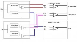
C1 high pass frequency will be affected by the position of the input pot.
When your sub volume is at the top the two opamp buffer outputs are connected to each other.
I do not think this is a good idea.
Your low pass filter should be fed from a low impedance source, not a variable impedance source pot (VR2). This will change the filter characteristics.
Assuming you are using split supplies the DC Signal Bias Resistor should probably be 0R0 IMHO.
Here is the method I used for my 2.1 boombox:
Attachments
C1 high pass frequency will be affected by the position of the input pot.
When your sub volume is at the top the two opamp buffer outputs are connected to each other.
I do not think this is a good idea.
Your low pass filter should be fed from a low impedance source, not a variable impedance source pot (VR2). This will change the filter characteristics.
Assuming you are using split supplies the DC Signal Bias Resistor should probably be 0R0 IMHO.
Here is the method I used for my 2.1 boombox:
Not my design, a reverse engineering of a popular 2.1 board from China. Yes, I had noted that when the sub pot is at maximum, the L-R op-amp outputs go from a passive summation to shorted. So I know not to turn the pot all the way up (and to use the L-R volume to balance).
It is a single supply board.
Agreed on the variable pot analysis but in practice, these audio taper pots (typically "B" if not "A" taper) are typically set at a fairly low impedance as the user is trying to extract maximum gain from weak phone outputs with the chip set at only 26 dB gain.
This might be stupid but has anyone tried to use xbox 360 psu to power this amp? My universal laptop charger is causing some trouble and I was thinking of modding old xbox psu to replace it. It should output around 200w at 12V
What's the gain of the chip on the board. You can have a 24v PS with 4 ohm speakers. If you not putting in a high enough signal vis-s-vis the chips gain setting, you won;t get the power out. See my paper on this.
View attachment 598660
I read it but don't fully understand. So i have to put the gain up. What is that gain? With bleutooth it go harder because of the higher input signal, but is this the same as gain or do i have the look somewere else on the board?
This was in answer to my query whether I could use a 3116 2.1 amp to power up a bucket sub (post #9808):
I've since built the bucket sub and am delighted with the results. I have a fairly small listening area and typically listen at fairly low levels. The bucket sub has really filled in the bottom end, almost like a giant loudness switch, but with detail and plenty of punch if I wind it up a bit.
Considering the entire system is comprised only of a 24V 6A SMPS. a Sanwu 2.1 amplifier, a pair of JVC midi system speakers and the bucket sub, I'm well satisfied with the results, and the cost.
My remaining issue is with the pop that is generated on switch off, it's particularly loud in the sub, even with the volume pots turned down prior to switch off. Can one of the boffs on here help me to install a mute switch to overcome this? The amp I'm using is this one:
http://www.ebay.com/itm/121824376824?afsrc=1&rmvSB=true
Ed, their inventor says 300 watts and his will rattle the windows next door.
I use a 300 watt plate amp but I think you could get by with less.
I've since built the bucket sub and am delighted with the results. I have a fairly small listening area and typically listen at fairly low levels. The bucket sub has really filled in the bottom end, almost like a giant loudness switch, but with detail and plenty of punch if I wind it up a bit.
Considering the entire system is comprised only of a 24V 6A SMPS. a Sanwu 2.1 amplifier, a pair of JVC midi system speakers and the bucket sub, I'm well satisfied with the results, and the cost.
My remaining issue is with the pop that is generated on switch off, it's particularly loud in the sub, even with the volume pots turned down prior to switch off. Can one of the boffs on here help me to install a mute switch to overcome this? The amp I'm using is this one:
http://www.ebay.com/itm/121824376824?afsrc=1&rmvSB=true
Last edited:
Did anyone tried this:
https://www.aliexpress.com/item/New...32699597173.html?spm=2114.13010308.0.0.iOTUPL
?
https://www.aliexpress.com/item/New...32699597173.html?spm=2114.13010308.0.0.iOTUPL
?
Did anyone tried this:
https://www.aliexpress.com/item/New...32699597173.html?spm=2114.13010308.0.0.iOTUPL
?
Hi,
I have two of those. Both work fine. Just check solder on caps, I had to reflux all.
Also did gain mod (reduced to 20 dB) because there was some noise with one of my sources.
I use them with 19V notebook bricks in active subs as replacement for dead amps.
Sound better than original 😀.
Hello, i have TPA3116 2.1 board (12v 50Wx2+100W TPA3116D2 2.1 HIFI digital subwoofer amplifier Verst board | eBay) thisdesing one. Having problem with hiss, I have read that it comes from L/R volume pot. So how do i remove the pot? I dont need it its always maxed.
- Home
- Amplifiers
- Class D
- TPA3116D2 Amp