Guys, can I humbly suggest you both drop it and we get back to the topic of this thread? I know what happened here and it was clearly a misunderstanding. I just went back through and both of you played a role. I don't care who's responsible and I don't think many watching this thread do either. Please just accept that and move on.
Understood and will do.
Hello everyone. Richard, I'm about to buy a new MC Magnetic Cartridge.
It is a DENON DL-110, with high output but of 1.6 mV.
It would need 48 dB to match Audio Technica's AT 440 MLa.
I need a preamplifier or you can increase the gain of the VSPS 300. Or I just hear it with a lower level ?. Can you tell the difference?
Greetings and I do not know if Christmas and New Year are celebrated on those sides. If so, Merry Christmas and Happy New Year !!
Hi Jose, Happy New Year.
1.6 mV is a a high-output MC type and covered by the VSPS circuit and any other standard MM phono stage (nominally for 1-7 mV output). The volume will be a little low, but 1-2 steps higher on the volume control will be sufficient to equalize the levels.
You could adjust the VSPS gain from 40 to 45 or even 50 dB. It's just one resistor (R2) to change, but I'd try it first as is to see if you feel it's necessary or not.
.................
I need a preamplifier or you can increase the gain of the VSPS 300. Or I just hear it with a lower level ?. Can you tell the difference?
.....................
If you can get enough volume by just turning up the vol pot then do not add extra gain...........................
1.6 mV is a a high-output MC type and covered by the VSPS circuit and any other standard MM phono stage (nominally for 1-7 mV output). The volume will be a little low, but 1-2 steps higher on the volume control will be sufficient to equalize the levels.
........................ but I'd try it first as is to see if you feel it's necessary or not.
Adding extra gain adds noise. If you don't need extra gain then don't add it.
It is better for system performance and for s/n ratios to operate the vol pot (attenuator) at near maxiumum, or even at maximum.
Thanks to both. I'll buy the Denon cartridge quiet. I'll tell you later. Happy Holidays.
Jose.
Jose.
I just received my Christmas presents. A bit late but still...
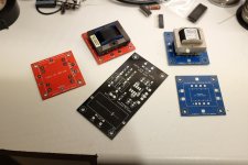
It's a VSPS without any onboard regs which I named with really 0 imagination "VSPS Solo".
The pcb is designed with AD797 in mind and a few parts that I like that did not fit properly on Richard's boards. Like Teflon RIAA caps, optional electrolytic coupling cap and a few others.
It still needs some work. Once I am happy with it I will send the files to Richard to do as he pleases with them. It really would not be fair if I sold these myself.
I also made a few boards for jensen and edcor transformers wired as autoformers to give around 6db of gain, the way NP used them on M2 and ZM on his Iron pre. It should be interesting to test how the sound ends up with some iron inline and bit more gain.
Attachments
"Thank you RJM Audio"😀 😀 😀
By the way all the Eagle .brd files for the VSPS and Phonoclone etc. can be downloaded from the pcb page, click the "download schematic" link.
So if you are up for it you can modify any of the boards to charge the package dimensions or add or remove features. Making the gerbers from the .brd files is simple, and some places will accept the .brd file anyway.
I mention this to point at that you don't have to go and completely redesign the board like dimkasta did if you don't want to.
I also do requests. So if you have something in mind, especially a modification to an RJM Audio project, feel free to run it past me.
Phoneclone 3
Hi all,
I had a go at building Richards phono stage clone, its a bit rough as I was using cases from a previous 'failed' project.
I'm keeping it as simple as possible at the moment - using an already existing external power supply - may ditch that it the future and populate the x-reg!!
No hum, as long as I keep any transformers away 🙂, and I've found that using no R1 resistor, ie just hard wired, with around 600-800 Ohm for R2 works best with my Dynavector DV17 MkII into my Naim pre.
Still experimenting, the Dynavector has a Internal Dc R quoted as 38 Ohms and outputs 0.23 mv.
Thanks to Richard for a great kit and a great service!
Attachments
![IMG_20170204_133140352_HDR[1].jpg](/community/data/attachments/534/534408-5254d42dbf727576e0b941411a04c787.jpg?hash=UlTULb9ydX)
![IMG_20170204_144219705_HDR[1].jpg](/community/data/attachments/534/534418-1831ddabef8757ebddf10c414035f0fb.jpg?hash=GDHdq--HV-)
![IMG_20170204_125040392[1].jpg](/community/data/attachments/534/534426-e30035a386d13a1247502aef04e67838.jpg?hash=4wA1o4bROh)
Thanks for the photos.
The power supply looks interesting. What circuit is it?
Ahh you've found me out already 🙂
Its an ebay kit - 'POWER-02 Adjustable linear Power supply kit' I saw it when looking for a dual rail supply - was looking to build a small power supply for my Naim Stageline - got it wrong as its a split rail and the Stageline needs dual positive rails. 😱
It works with the Phonoclone, but as a complete novice, I'm not sure how low noise it really is!
Hi, very good photos. I like the source of power. Which box model are you using? I ask about the size of the capacitors.
Greetings, Josè.
Greetings, Josè.
Hi, very good photos. I like the source of power. Which box model are you using? I ask about the size of the capacitors.
Greetings, Josè.
Thanks Josè.
The box size is referred to as 1506 - various versions of it, but the one I chose was -
New 1506 Silver Full Aluminum Amplifier Enclosure /Mini AMP Case/ Preamp Chassis | eBay
The power supply was the standard 'power-02' -
Standard POWER-02 Adjustable pre-linear Power supply kit for preamp | eBay
I changed the smoothing Caps to 10,000uf, to be honest, no reason other than they fitted the space on the board better - maybe I'll revert to the supplied ones!
regards
Robert
Thank you Naimart. I have just that box with a 50-watt toroidal transformer. My doubt is the height, because I see two capacitados 10,000 microfarads and I thought they would not fit in that box. Greetings and thanks. Joseph.
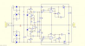
The power supply circuit, according to Google. 😉
Pretty simple series voltage regulator with adjustable output. You wonder if the schematic was lifted from a commercial benchtop power supply.
The only thing I don't follow is the purpose of the jfets "R24, R14".
Pretty simple series voltage regulator with adjustable output. You wonder if the schematic was lifted from a commercial benchtop power supply.
The only thing I don't follow is the purpose of the jfets "R24, R14".
Attachments
Last edited:
The two jFETs are set to operate as CCS.
They pull a constant current from the output pin to the supply rail. This turns the push pull output stage inside the opamp into a form of single ended., when the output load current is << CCS current.
Many opamps work a bit better when one of the internal devices in the push pull output stage are in effect crippled by the CCS to supply rail. All opamps have a preference for whether the CCS is to the +ve supply rail, or to the -ve supply rail.
That circuit shows the two opamps each with a CCS to different supply rails.
I think the circuit Designer forgot to go to bed the night before.
Last edited:
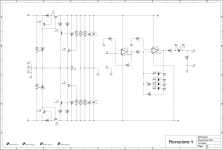
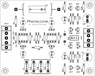
Phonoclone 4
It's been quite a few years since I last took a serious look at the phonoclone circuit.
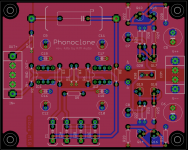
Presenting the Phonoclone 4. The basic circuit is the same, but the X-reg has been substituted for the S-reg shunt-series regulator and the layout has been completely redone. The mounting holes have been changed to the 70x90 mm used in my Sapphire headphone amp and all my recent board designs.
It's been quite a few years since I last took a serious look at the phonoclone circuit.
Presenting the Phonoclone 4. The basic circuit is the same, but the X-reg has been substituted for the S-reg shunt-series regulator and the layout has been completely redone. The mounting holes have been changed to the 70x90 mm used in my Sapphire headphone amp and all my recent board designs.
Attachments
Won't know until the boards are made. Most of the changes are convenience or tidy-ups rather than sound quality, only the voltage regulation has changed.
I think the shunt regulation will sound better.
I think the shunt regulation will sound better.
I'd like some opinions on a couple of things before I go ahead and get the boards made.
1. Can I go ahead and change the mounting holes to the my new metric standard or do people want the old inch spacing (2.5" x 3.5")? It means people wanting to upgrade will have to drill new holes for the standoffs. There is room to move the holes to the old position, and I can do a small batch in the old format if there is the demand.
2. I really like trim pots, in this case R30 just allows the V+ and V- rails to be adjusted to be exactly symmetrical. Without it depending on the transistor V_be missmatch the voltage rails might be about 0.5 V different. Trim pots though seem to bring anxiety and stress to a lot of people diyaudio. I can leave it out if people prefer.
3. I think the best option for people wanting multiple values of R1 and R2 is sockets or standoffs. I considered DIP switches (no room) or jumpers (still cramped) and felt that it wasn't worth it: people either are OK with one setting or will want the flexibility of more than two options so the jumper idea is unlikely to please anyone.
Advantages of new board:
- lower parts count, lower BOM cost
- standardized I/O connections allowing screw terminal blocks
- shunt regulators, built-in overcurrent protection, uses TO-92 instead of TO-126 transistors so less likely that people wire them up backwards
- a more rational layout
- standardized mounting holes, common to CrystalFET, Sapphire, etc
Come to think of it given the amount of problems this has caused over the years I should probably add a pair of diodes to protect the caps from people connecting V++ to power supply V--.
- Home
- Source & Line
- Analogue Source
- The Phonoclone and VSPS PCB Help Desk