...that I fear for my CD/tweeter...
Oh fingers XX...ed here your babies survive and make one smile again, will get back comments previous post 279.
Last edited:
Meanwhile, I'm thinking about how to implement a power off delay for the DSPs. I could power them from an UPS, uninterruptible power supply, but what if the DSP chips crash while they are idling?
I just checked and saw that the single point TDA DFR with FIR on is a close match in shape to the DFRe predicted by TDA EQ but the absolute value of delay measured on the shelf is less than half that predicted. Curious.
The AFR isn't such a good match to the AFRe but the AFRe has the benefit of the averaging process filtering out the room. The AFRq from TDA, even with a Q=1.8 narrow window, still shows a lot of the room.
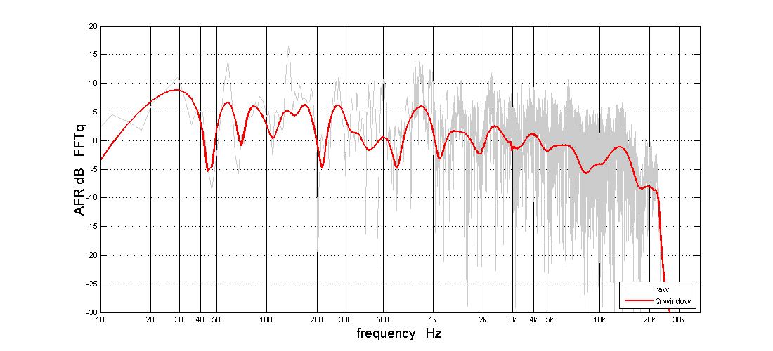
The AFR isn't such a good match to the AFRe but the AFRe has the benefit of the averaging process filtering out the room. The AFRq from TDA, even with a Q=1.8 narrow window, still shows a lot of the room.
Attachments
The issue about the response at 1 Khz is still open. Is that the XO's group delay we are seeing there or due to the room?...
Take suggestions with a gran of salt : ) and have in mind my own room acoustic isn't as good as yours and wesayso's so have not real experience to calibrate out at LP, mine is near field calibrated, so really don't like to steal your time Jack looking into wrong clues but can think about three things that could influence that area and maybe worth investigate.
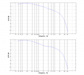
One is the slopes from post 277 how does it look near field and how does it look at LP and does it make sense if there's difference, first attachment is AFR for perfect IR 15Hz-20kHz with B&K curve where second is same but with your IIR XO points and it predicts a little dip verse your peak.
Second is the one you catched in previous post meanwhile i write this post : ) where it looks like linear phase for 350Hz XO point even its IIR. Can be seen in second attachment which is same perfect IR verse real world, also TDA pl show that woofer is looking fire too early for this type IIR XO pulling mids timing in advanced direction instead of lacking direction. Isolated seen it looks good as is with lovely flat phase but in knowing used XO type at present is IIR type its curve is not by the book.
Third is that because its a peak that shows there reminds me when WinspeakerZ sim 4th order symmetric band-pass it always plot a huge peak, haven't any experience real world with executing 4th order symmetric band-pass and see most use HR to calculate response, but can it be there is such a hidden narrow high q resonance from mids that needs some strategic massage to get smooth.
By the way your nice APL software demos and talk via PM made me yesterday spend some savings and get new software, look forward playing with strategic auto correction.
Attachments
Meanwhile, I'm thinking about how to implement a power off delay for the DSPs. I could power them from an UPS, uninterruptible power supply, but what if the DSP chips crash while they are idling?
Have some DEQ2496 from Behringer that mostly used for guitar setup but had a time where they did my XO's, about DC thumbs they have smart AC steered relays that short audio output when relay is in rest position, that means if any live power loss happens or one turn off unit at mains button audio output is shorted immediately, and when main power gets back either after a power plant failure or user turn on mains button there's a logic delay circuit that opens relay so late that all circuits had plenty time to settle into silent operation mode.
Hi BRYTT:
re' Isolated seen it looks good as is with lovely flat phase but in knowing used XO type at present is IIR type its curve is not by the book.
I agree on both parts - its lovely but not by the book. I tend to focus on the former rather than the latter 🙂 I blame the latter on the room. And I want to work on the room to remove that excuse. I really wish I could have taken these speakers, the tops anyway, outside for a measurement.
re' bandpass mids
I too use HR for the bandpass mids simulation and so I'm looking at power rather than SPL unless I go to extra trouble in my simulation. I tuned my mid ports for a broad response, not highly peaked like you showed but I still have to attenuate the peak severely to get a flat response. I think any resonances would be attenuated as well.
Don't forget the reflection off the compression driver diaphragm causes a null at around 1.4 Khz. Can you see this in any of the graphs? I haven't looked but I doubt it. I've got the chamber tuned to minimize the width of that null - to the point where it disappears in simulation leaving only a phase discontinuity. That could be the "hidden high Q resonance". If so, its outside the mid pass band.
There has always been troublesome reflections around 1 Khz, both down in my garage at first and up in the listening room where the speakers are now. Going through a measurement with a series of different time gates, the response continually changes in throughout the mid passband. I think its from the floor and ceiling but there might be an additional source contributing. This again makes me wish I had taken them outside for measurement.
Thanks for your posts that always make me think and have fun with your new software.
Jack
Have some DEQ2496 from Behringer that mostly used for guitar setup but had a time where they did my XO's, about DC thumbs they have smart AC steered relays that short audio output when relay is in rest position, that means if any live power loss happens or one turn off unit at mains button audio output is shorted immediately, and when main power gets back either after a power plant failure or user turn on mains button there's a logic delay circuit that opens relay so late that all circuits had plenty time to settle into silent operation mode.
relays: wouldn't there be a race to open/close the contacts before the noise spike got through to the speakers? are they solid state or mechanical?
I get in trouble when I shut off the DSP at the same time or before the amps.
No problems powering on because the amps have a turn on delay built in.
I just want something to keep the DSP output sane after mains power is switched off until the amps use up all the charge on their own power supply capacitors. Probably don't need more than 10 seconds
Now that I think about it, a really big capacitor on the DC power to the MiniDSP should do just that. hmmm
...And I want to work on the room to remove that excuse. I really wish I could have taken these speakers, the tops anyway, outside for a measurement.
...
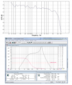
Probably always best place to first improve speaker acoustic but suggest edit delay in miniDSP for woofer lacking approximate 2,5mS as seen below, it will not be much waste of time if it doesn't work : )
Attachments

Last edited:
relays: wouldn't there be a race to open/close the contacts before the noise spike got through to the speakers? are they solid state or mechanical?
I get in trouble when I shut off the DSP at the same time or before the amps.
No problems powering on because the amps have a turn on delay built in.
I just want something to keep the DSP output sane after mains power is switched off until the amps use up all the charge on their own power supply capacitors. Probably don't need more than 10 seconds
Now that I think about it, a really big capacitor on the DC power to the MiniDSP should do just that. hmmm
Agree as simple as possible would be nice : )
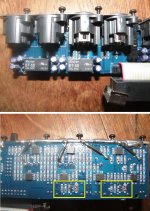
Had some pictures from past just before mod output to DC coupled single ended, we can see relays there but okay they say 5v DC. Their steering circuit most then feel on AC line somewhere or small trafo into SMPS because they abrupt switch to contacts resting position and no thumb reach audio output which saved me several times : )
My present setup is quite noisy when power plant failure but in using SS 10F as mid-tweeters that on paper allow 7mm Xpeak it seems no dangerous problem.
Attachments
Agree as simple as possible would be nice : )
Had some pictures from past just before mod output to DC coupled single ended, we can see relays there but okay they say 5v DC. Their steering circuit most then feel on AC line somewhere or small trafo into SMPS because they abrupt switch to contacts resting position and no thumb reach audio output which saved me several times : )
My present setup is quite noisy when power plant failure but in using SS 10F as mid-tweeters that on paper allow 7mm Xpeak it seems no dangerous problem.
You should be safe enough. Drivers can be pretty robust. My CDs can handle 65W RMS, 450W peak and my amps are only 125W but to be safe I recently
bought four 5 ohm power resistors to make passive attenuator (about 9 db) to protect them. Should have wired them in yesterday.
Q
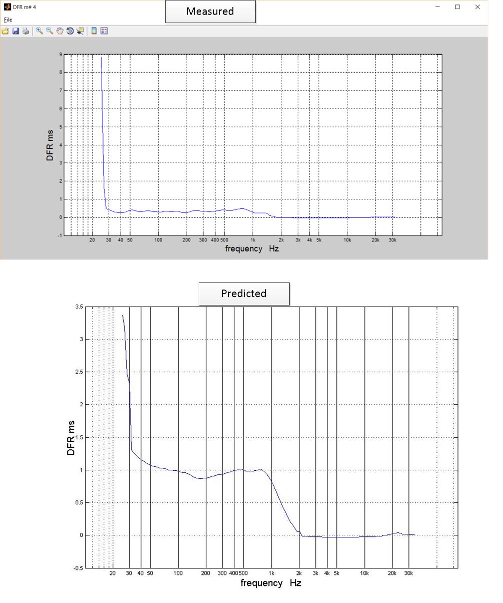
Does the upper graph come from the synthetic IR you posted? Did you notice how you get different pictures with different Q values and with and without min phase subtracted. Confusing isn't it?
I recognize that the lower graph is a GDR with min phase subtracted, but I'm not sure which one. OTOH, here is a TDA DFR that is a pretty good match to the upper graph:
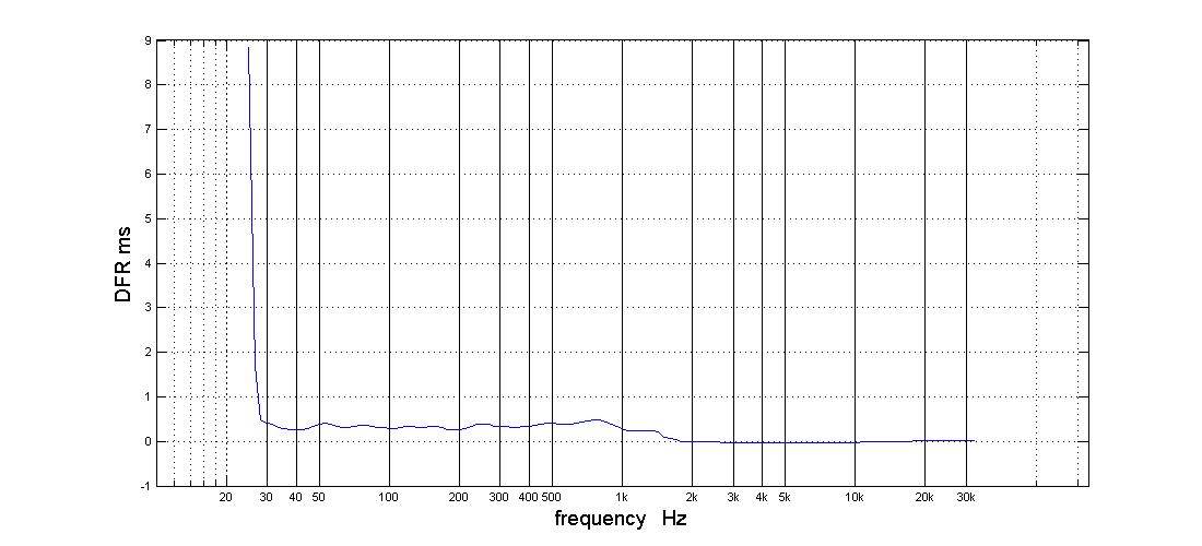
that was measured at the favorable listening position with the TDA EQ FIR on.
Recall that tda eq doesn't give you a GDR curve; just a DFR. TDA does both. I don't know what the difference is other than GDR has Q-windowing.
Given the DFR matches the synthetic IR's GDR, do you still think I need to change the woofer's delay? In point of fact, the woofer delay is zero. Its the other drivers that are delayed to align with it.
by 2.35 ms for CD and 2.06 ms for mids
Jack
Probably always best place to first improve speaker acoustic but suggest edit delay in miniDSP for woofer lacking approximate 2,5mS as seen below, it will not be much waste of time if it doesn't work : )
Does the upper graph come from the synthetic IR you posted? Did you notice how you get different pictures with different Q values and with and without min phase subtracted. Confusing isn't it?
I recognize that the lower graph is a GDR with min phase subtracted, but I'm not sure which one. OTOH, here is a TDA DFR that is a pretty good match to the upper graph:
that was measured at the favorable listening position with the TDA EQ FIR on.
Recall that tda eq doesn't give you a GDR curve; just a DFR. TDA does both. I don't know what the difference is other than GDR has Q-windowing.
Given the DFR matches the synthetic IR's GDR, do you still think I need to change the woofer's delay? In point of fact, the woofer delay is zero. Its the other drivers that are delayed to align with it.
by 2.35 ms for CD and 2.06 ms for mids
Jack
Attachments
Does the upper graph come from the synthetic IR you posted? Did you notice how you get different pictures with different Q values and with and without min phase subtracted. Confusing isn't it?
I recognize that the lower graph is a GDR with min phase subtracted, but I'm not sure which one. OTOH, here is a TDA DFR that is a pretty good match to the upper graph:
that was measured at the favorable listening position with the TDA EQ FIR on.
Recall that tda eq doesn't give you a GDR curve; just a DFR. TDA does both. I don't know what the difference is other than GDR has Q-windowing.
Given the DFR matches the synthetic IR's GDR, do you still think I need to change the woofer's delay? In point of fact, the woofer delay is zero. Its the other drivers that are delayed to align with it.
by 2.35 ms for CD and 2.06 ms for mids
Jack
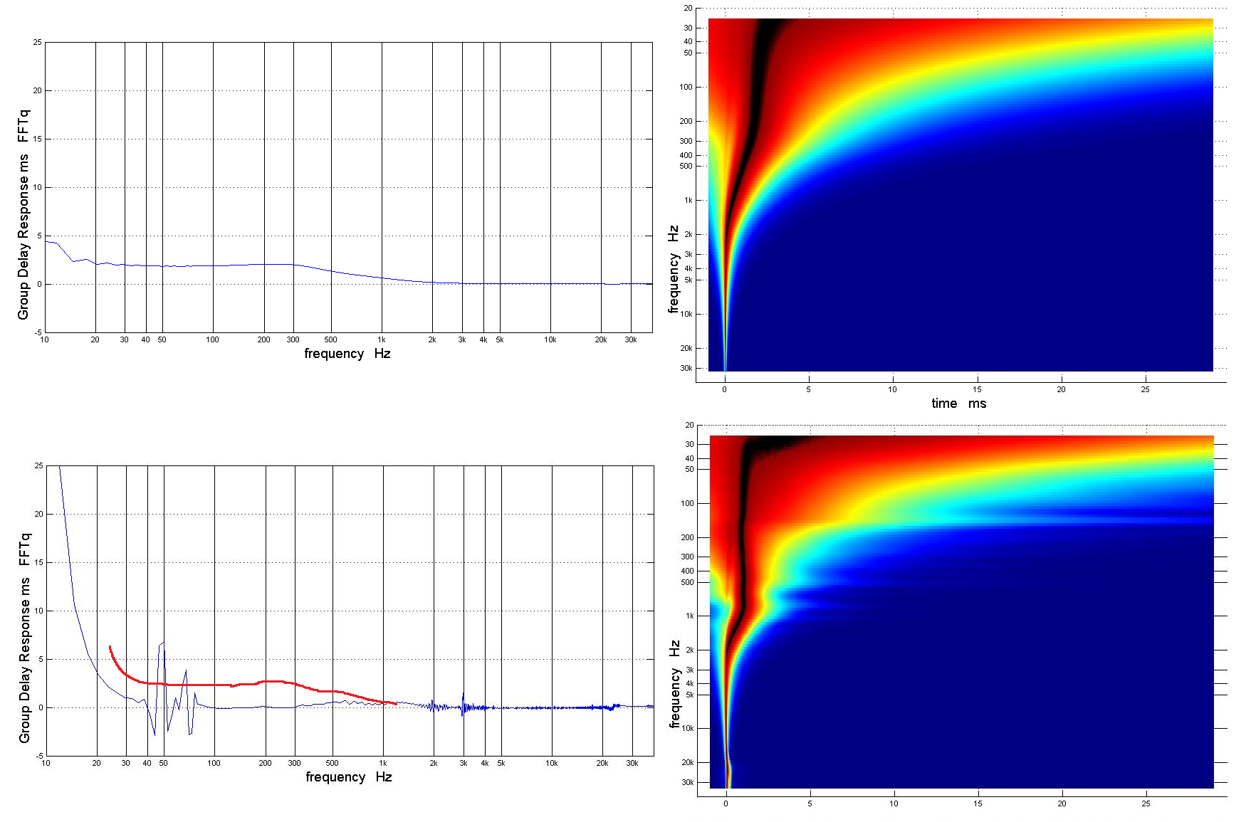
But this morning what I had been missing popped into my head. Yesterday, I posted measurements of the FIR-corrected speaker response. No longer is the synthetic IR with 24 db acoustic slopes the theoretically correct response - its been "corrected". The red line you added to the lower drawing shows how much and where it has been corrected.
Raimonds told me:
The source of DFR is black edge of TDA 3D graph. It is clearly time.
The source of GDR is Phase FR obtained by FFT from windowed IR.
Jack
Hold on a second before take posting below for granted : )
For me seek statement are XO points at 350Hz and 950Hz IIR or FIR filters, if they IIR XO points below trial for set woofer delay in 2-2,5mS area should be good enough try out. Could be wrong but think not TDA_EQ do only time domain correction so a IIR XO point gets invisible, but if it does why then is 950Hz XO point still so visible in TDA plots (black edge in 3D graph).
Does the upper graph come from the synthetic IR you posted? Did you notice how you get different pictures with different Q values and with and without min phase subtracted. Confusing isn't it?
I recognize that the lower graph is a GDR with min phase subtracted, but I'm not sure which one. OTOH, here is a TDA DFR that is a pretty good match to the upper graph:
that was measured at the favorable listening position with the TDA EQ FIR on.
Recall that tda eq doesn't give you a GDR curve; just a DFR. TDA does both. I don't know what the difference is other than GDR has Q-windowing.
Given the DFR matches the synthetic IR's GDR, do you still think I need to change the woofer's delay? In point of fact, the woofer delay is zero. Its the other drivers that are delayed to align with it.
by 2.35 ms for CD and 2.06 ms for mids
Jack
Good thing to have sorted out if there's any misunderstandings the many graphs posted : )
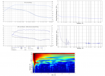
Did a recheck and confirm lower left graph are from post 279 that is noted "with min phase subtracted" same setting was ticked for upper synthetic target above it, by the way repost it below but with some X/Y axis numbers plotted, upper TDA pl is the synthetic target and lower TDA pl is yours (TDA_EQ) at LP from post 268 noted "post equalization graphs".
So still think would be interesting to see woofer added some delay in it looks like at GDR plot (not TDA pl) its in synch with CD and pull mids natural lacking direction in advance. Have seen strange things ín this subject what one thinks looks logic step ruin some other but its so easy try it out and get some new data so stir into. If it turns out to be move in right direction setting delay for woofer at 2,0mS then in length probably better edit the other bands too so one of them is at zero delay.
Attachments
Last edited:
Away from my pc....Hold on a second before take posting below for granted : )
For me seek statement are XO points at 350Hz and 950Hz IIR or FIR filters, if they IIR XO points below trial for set woofer delay in 2-2,5mS area should be good enough try out. Could be wrong but think not TDA_EQ do only time domain correction so a IIR XO point gets invisible, but if it does why then is 950Hz XO point still so visible in TDA plots (black edge in 3D graph).
Good thing to have sorted out if there's any misunderstandings the many graphs posted : )
Did a recheck and confirm lower left graph are from post 279 that is noted "with min phase subtracted" same setting was ticked for upper synthetic target above it, by the way repost it below but with some X/Y axis numbers plotted, upper TDA pl is the synthetic target and lower TDA pl is yours (TDA_EQ) at LP from post 268 noted "post equalization graphs".
So still think would be interesting to see woofer added some delay in it looks like at GDR plot (not TDA pl) its in synch with CD and pull mids natural lacking direction in advance. Have seen strange things ín this subject what one thinks looks logic step ruin some other but its so easy try it out and get some new data so stir into. If it turns out to be move in right direction setting delay for woofer at 2,0mS then in length probably better edit the other bands too so one of them is at zero delay.
Look back a few pages and you will see horn resp sim or graph that shows that woofer has 2 ms. or so of horn path to traverse and that is why mods are delayed 2me.
Not to say it wouldn't be interesting to see effect of giving a head start to the "slow" woofer
Noo, delay it... the woofer that is...
Also, the transition of tweeter/mid seems to be a little long for LR4. I've played with sims that showed me ~0.5 to 0.6 ms delay when setting it up with perfect speakers (virtual ones obviously).
Also, the transition of tweeter/mid seems to be a little long for LR4. I've played with sims that showed me ~0.5 to 0.6 ms delay when setting it up with perfect speakers (virtual ones obviously).
Noo, delay it... the woofer that is...
Also, the transition of tweeter/mid seems to be a little long for LR4. I've played with sims that showed me ~0.5 to 0.6 ms delay when setting it up with perfect speakers (virtual ones obviously).
I'm not going to change the woofer-relative timing. I'm a firm believer in "if it's not broken, don't fix it"
What do you see in the charts that makes you say the transition is too long for LR4? Don't forget that when I first made the crossover, I equalized to LR4 target curves down at least 15 db. I may have strayed from that subsequently but subsequent PEQ changes were small.
If you are referring to the width of the ~1 Khz dip in the tda_EQ AFRe, then I would say that is an argument that the dip isn't due to the crossover. Something is happening in the room that transforms a small bump in a 1m measurement to a dip in the AFRe at the LP.
If you look at the light gray traces in the FFT-q AFR, or at the all AFR curves from TDA_EQ, you will see that there are indeed reflections being summed in there. I need to make a greater effort to find and eliminate the source of those particular reflections. I probably determined that earlier but didn't do anything about it thinking I had worse things to worry about.
Jack
It's timing if you ask me that transforms the bump close up to a dip at further distance...
I believe you have the proper slopes. But it also needs the right timing to sum at the crossover point. If it's slightly out of phase it will still sum.
If you're happy with it, no problem. It's only looking at these graphs that tells me this story. You're pretty close anyway.
I believe you have the proper slopes. But it also needs the right timing to sum at the crossover point. If it's slightly out of phase it will still sum.
If you're happy with it, no problem. It's only looking at these graphs that tells me this story. You're pretty close anyway.
But I was asking which graph you were looking at what did you see on that graph. Not questioning your conclusion but trying to understand what led you to it.
OTOH, this is a Synergy horn in which I followed all the rules so timing shouldn't change with distance. That will happen between the horn and the woofer but not within the horn between the CD and the mids located within 1/4 lambda of it at xo.
OTOH, this is a Synergy horn in which I followed all the rules so timing shouldn't change with distance. That will happen between the horn and the woofer but not within the horn between the CD and the mids located within 1/4 lambda of it at xo.
The TDA plots are showing you the timing. Look at the plots from BYRTT which represent the ideal. You see a more gradual shape above and below the crossover frequency. That means it sums a little different than what you have.
I'd give the mid just a little less delay, relative to the tweeter and see.
The second crossover between mid and woofer shows no time delay at all, which usually does not happen with IIR crossovers. Again, look at the example from BYRTT.
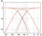
If you have EQ-ed the shape of the FR to follow an LR4 crossover on the CD tweeter and the mid, both phase curves should line up perfectly at the crossover point. The phase would still be equal above and below that crossover point, making the timing look like the top example in this plot:
I'm not getting on your case here... but if the timing is slightly off, it will still sum in a plot like this, but phase above and below the crossover will not line up as it should in a textbook manor. Which shows up as a slight dip in the frequency at 1-2 KHz.
The textbook example shows a time change starting at ~3 KHz, yours is a more abrupt
corner later on, which means the phase curves don't line up.
I think BYRTT was saying the same thing, judging by his edit in the bottom example. I'm just looking at the graphs and numbers (time delay).
I'd give the mid just a little less delay, relative to the tweeter and see.
The second crossover between mid and woofer shows no time delay at all, which usually does not happen with IIR crossovers. Again, look at the example from BYRTT.
If you have EQ-ed the shape of the FR to follow an LR4 crossover on the CD tweeter and the mid, both phase curves should line up perfectly at the crossover point. The phase would still be equal above and below that crossover point, making the timing look like the top example in this plot:
I'm not getting on your case here... but if the timing is slightly off, it will still sum in a plot like this, but phase above and below the crossover will not line up as it should in a textbook manor. Which shows up as a slight dip in the frequency at 1-2 KHz.
The textbook example shows a time change starting at ~3 KHz, yours is a more abrupt
corner later on, which means the phase curves don't line up.
I think BYRTT was saying the same thing, judging by his edit in the bottom example. I'm just looking at the graphs and numbers (time delay).
Last edited:
Hi wesayso looks for me we see and say the same thing.
Jack think its complicated area try look down -40dB all three drivers is summing there mid looks like kind of filler driver, to sum smooth that area and not have any peaks and dips all three needs prescription for own slope and precise timing.

Jack think its complicated area try look down -40dB all three drivers is summing there mid looks like kind of filler driver, to sum smooth that area and not have any peaks and dips all three needs prescription for own slope and precise timing.
Attachments
Last edited:
- Home
- Loudspeakers
- Multi-Way
- My Synergy Corner Horn and Bass Bins