and that is why you would mount the devices in an asymetrical arrangement to try to equalise the interface temperature of the devices.
I would do that, but this not my equipment 🙂 This is one example for Fischerelektronik website.
Sajti
Sanken and a long time later Onsemi manufactured power devices with diodes integrated inside the package to allow for this quick repsonding tempco.
Unfortunately the pinout of these NJL1302D/3281D ThermalTrak devices in their TO264-5 packages reads B-E-C-A-K (with K for the diode's cathode). If it were B-A-C-K-E, i.e., if the diode pins were put right between the usual pins of a TO264-3 package, we were able to use them in a Honey Badger build, by bending the diode associated pins of four devices forward and hand-wire them as a substitute for the Vbe multiplier.
Best regards!
Try to do some measurement! It's better to mount above than side by side. But it must close of course.
The convecting air is not as warm as the heatsink, but it's not cooling donw the heatsink as much as where it's cold. Check out the right side of the picture attached!
This is mesurement of the heatsink with left to right forced cooling. The temperature is significant higher at the output of the air.
I never doubted that. I just said that the heatsinks temperature cannot be higher above the devices as in the area where the devices are mounted. Your drawing clearly depicts this.
Maybe I've just misread, or misunderstood, your previous posting.
Best regards!
I just said that the heatsinks temperature cannot be higher above the devices as in the area where the devices are mounted
That is true. But You are not able to mount the Vbe multiplier to the same footprint, if You are not the Onsemi 🙂
Sajti
That's why I have only used 6 pairs. To fit a pair Roender amplifiers.Unfortunately the pinout of these NJL1302D/3281D ThermalTrak devices in their TO264-5 packages reads B-E-C-A-K (with K for the diode's cathode). If it were B-A-C-K-E, i.e., if the diode pins were put right between the usual pins of a TO264-3 package, we were able to use them in a Honey Badger build, by bending the diode associated pins of four devices forward and hand-wire them as a substitute for the Vbe multiplier.
Best regards!
I so far have only built on group buy PCBs from this Forum and no one uses the NJLs.
Oh, and they're expensive, too, calling about 1.5 times the price of their MJL counterparts (@Mouser).
Best regards!
Best regards!
Do you think I bought 24pairs because they were expensive?Oh, and they're expensive, too, calling about 1.5 times the price of their MJL counterparts (@Mouser).
Best regards!
Come on, I'm a scotsman.
I bought them because they were much cheaper than their three legged equivalents.
edit,
Just went upstairs to check, and I'm right, I'm getting too old for this. I bought 100 pairs and only have 94 pairs left.
Last edited:
Do you think I bought 24pairs because they were expensive?
Come on, I'm a scotsman.
I bought them because they were much cheaper than their three legged equivalents.
Ha ha!
What exactly were the parts that you bought? When did you buy them? My price comparison based upon research I did right before my last posting. Maybe they were much cheaper those days.
What are you planning to do with these many transistors? Perhaps you might want to sell some of them?
Best regards!
It was just before I became aware that Onsemi were going to discontinue their NJL line up.
A retailer must have been wanting to sell off stock before he got stuck with obsolete parts.
I can't remeber the price paid but it was around 50% of the bulk buying price at that time, so I jumped in with all my feet.
They are NJL1301/3281
I selected out the first few pairs and measured them up to find good triplets to put into the two Roenders. It is a 3pair output stage.
When I get around to matching up pairs and triplets and have thus "added value" I may sell spares. If not, they and all my other techy bits are already in my will to go to my former high school. It depends on who grabs me first.
Short update: mounting Q13 above power devices (5mm above) gives the following result in comparison to position between Q14/Q15. Surprisingly negligible.

Did You try to reduce the bias current manually as the temperature rise? Just turn it down to the recommended as the heatsink is hot.
Sajti
Sajti
That would be contradictory to one of the two Vbe multiplier's main purposes, wouldn't it?
There must be something wrong in his build, as others, supposedly those using the PCBs from the DIYAudio shop, don't observe (or report, at least...) this issue. The more I'm thinking of it, the more I come to the conclusion that the leads between the BJT's and the board might be too long, too thin, or the connectors might be too unreliable, or whatsoever.
Best regards!
That would be contradictory to one of the two Vbe multiplier's main purposes, wouldn't it?
Sure, but I saw some Marantz manual, which stated to set the cold bias to 20mA, and it will increase to 50mA as the amplifier heating up...
Sajti
Sorry, but I didn't manage to find any hint on the Honey Badger in your Marantz manual.
Best regards!
Best regards!
Since the amp works really fine (I listened to music with it for a couple of hours) I doubt anything is wrong with the circuit or the connectors. Also high currents were no problem. No oscillation observed so far.
To what I have understood so far concernig bias stabilization, it shoudn't be possible at all to reach full /perfect temp compensation (nevertheless pretty close to it with sensing diodes in the power devices.
My measurements show what you can expect from theory: the better the thermal coupling the better the compensation. A thermal overcompensation shouldn't be possible with the honey badger type of bias spreader - in my theoretical understanding.
Sajti, I have no higher hfe Q13 available to try it out. But according to my math a couple of posts before, I dont see how this could help. In my inderstanding, the voltage devider comprising R28/R29/R30 or rather the current flowing through them need to fit to the hfe and hence Ib. In my case I would regard Ib as negligible to influence the compensation, isn't it?
Sorry, but I didn't manage to find any hint on the Honey Badger in your Marantz manual.
Best regards!
Of course, but
both of the are using BJT output? Yes.
both are using EF output stage? Yes.
both are Vbe multiplier to set the bias? Yes.
Is there any relation between them? Yes.
Anyway to try my idea cost nothing, and not complicated... Why not try it???
Sajti
In my inderstanding, the voltage devider comprising R28/R29/R30 or rather the current flowing through them need to fit to the hfe and hence Ib. In my case I would regard Ib as negligible to influence the compensation, isn't it?
Running more current over the Vbe transistor increase the compensation. Running more current over the setting resistors, will reduce the compensation.
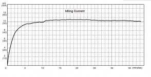
Here is one real measurement, how the bias current change from turn on, in the Marantz MA9.
Sajti
Attachments
Sajti, I have no higher hfe Q13 available to try it out. But according to my math a couple of posts before, I dont see how this could help. In my inderstanding, the voltage devider comprising R28/R29/R30 or rather the current flowing through them need to fit to the hfe and hence Ib. In my case I would regard Ib as negligible to influence the compensation, isn't it?
I totally agree with you. To confirm that, and/or just for fun, you could drill a 5 mm hole into the heat sink, next to the power deivces, glue (or use thermal compound) a high hfe TO-92 device (BC550C would do) into it, use this one as the Vbe multipler, increase the divider's resistance values by a factor of, let's say, 5, take measurements as before and report.
Best regards!
Ok. This depicts thermal behaviour (thermal stability, in this case) over time, but it doesn't tell us anything about stability over temperature, which is Zymorg's issue.Here is one real measurement, how the bias current change from turn on, in the Marantz MA9.
Before coming to general conclusions, you have to check literally any details, such as
- the operating points (is the MA9 running on class AB, as the HB does, or is it plain class B?)
- the driver/output configuration (is the MA9 a double emitter follower like the HB, or are there any Sziklai pairs, or is it even a quasi complementary design?)
- where is the MA9's Vbe multiplier device located? To the heat sink, as in the HB?
- etc.
Any other is comparing apples with oranges.
Best regards!
Last edited:
- Home
- Amplifiers
- Solid State
- diyAB Amp The "Honey Badger" build thread