Then designing a new PCB is an effective and efficient solution. Larger parts could be used while keeping more or less the supposedly good layout. Then comparison with original boards, be it with or without mods.
Last edited:
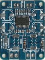
Bigger package bootstrap c16 is (337) 330nF, curiously bootstrap c25 also is (347) 330nF even a little higher. Two mistakes next to each other ? Weird. Close to chippin decoupling ~92nF so 100nF (5v meter bias, tollerance), more distant decoupling 1nF (1.007 both actually LOL). Back to doing something usefull now 🙂
What is funny chip? May you try to improve your understandability, please?
Differ to what? Do they or don't they? What does "seems" mean here?
bootstrapceramic sizes seem to differ
Differ to what? Do they or don't they? What does "seems" mean here?
I wonder why no one complains about missing bootstrap-snubbers. Back in the days this was the most done mod with "huge" improvements in treble.. 😀
Doesn't matter anymore?
Doesn't matter anymore?
It is called "information-fatigue" or "information overload".
If many think this is a very good or even the best sounding board it apparently does not need these parts. Or the lack of those parts is why you see strange phenomenons on your scope 🙂 Others have simply lowered gain to 20 dB, connected them, think they sound good, enjoy some music and have a drink.
* It could be GND induced spurious radiation that won't occur with TPA3128 as it has some special LDO in AVCC compared to TPA3118 EVM with AM1 set to high. Or something like that.
Last edited:
I wonder why no one complains about missing bootstrap-snubbers. Back in the days this was the most done mod with "huge" improvements in treble.. 😀
Doesn't matter anymore?
I vertically mounted 0805 bootstrapsnubbers, but even that size is small and space tight.
c16 is bigger sized 0603, physically, negative output bootstraps just 220nF btw.
Attachments
Last edited:
You will I hope 😀 It makes me happy to think of yet another 100 pages with cross referencing and diagrams. Preferably with as many other chips, cap properties and data sheet abbreviations as possible interfering in between.
Last edited:
I don't have a way of measuring.
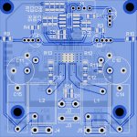
Are the generics and Sanwu 2oz copper? Or a variant 1.5oz ?
On audio quality , I go for a low thd too but as a final metric listen to 'Red Bar Jazz Band', tracks 2 and 5.
On track 5(every day i have the blues) listen and focus on the cymbals with an AB hi-fi then listen with the TPA3118. I used the Uni-Q Q10 pair in parallel with one 3118 generic. Someone told me on a thread that the Q10 is labeled 6 ohm but more like 3-4 ohm. So maybe looking at 2-3 ohm load.
I used the Dragonfly as DAC with lossless bit packed m4a files.
-bruce

Doctormord is doing great work and big favor for the community here with all the measurements and graphs. To me methods used and reasons for them sound well justified. The topic is not easy and the learning curve is steep, one can not blame the messenger for that.
Irribeo is pointing out valid things. Some might have effect, nobody knows for sure before someone measures it. They will bring more variables, but do we really need to be afraid of that? To max out anything one must turn every rock to find improvements.
After reading and thinking I don't see much sense in modding the existing mono boards (sanwu or clone). There is just too many things wrong with them, dubious parts and non ideal layout. Changing inductors helps, but the recorded performance is there only IF you have genuine TI chip and I bet most cases you don't (I do hope I'm wrong). So basicly one buys a board for ~4€ to desolder all main parts on it.
I think that money and time would be better spent on ordering plain board from fab with bootstrap mod, decent pads for inductors, places for film caps where needed, etc. Cost would probably be about same for one board when ordering 10pcs. Ordering main parts (IC, coils, caps) from reliable source would give peace of mind and rest of the parts don't cost much anyway. Example budget of 25€ for one channel given by jean-paul would probably be easily met.
At the moment I don't feel too confident about soldering small IC legs so close together, but if good layout is ever released I might be tempted going through the whole process described above (with layout I mean gerbers).
In the mean time, what system doctormord are you using for measurements? 🙂
I use am EMU-0202, which has 2 true differential inputs, and Arta. You can get these boxes used at Ebay for a good price.
Still trying blue 🙂
This next tpa3128/18 pcb would be around $28 BOM (Mouser) per mono pcb, Nichicon ES bipolar on input, Wima film adds around $5.
This one with opamp phase splitter and post filter feedback as tpa3251evm. Opamp phasesplitter is a benefit for single ended sources, even without the feedback that might not work with tpa3128 properly. Opamps can be noisy if layout is bad, so here it might be terrible 🙂 IceComponent 1D14 inductors. 50mmx50mm and two standoff mounting holes below polyprop outputcapacitors, so mounting sequence would be important 🙂
Attachments
Nice board but tell me ho the mounting sequence should be as I think it is impossible to mount those screws 🙂 When you screw the screws in standoffs the caps will be soldered in not flush with the PCB. If you mount the board to the chassis and one of the standoffs comes loose it will be hard to correct.
Nice to design ultra small boards for the chinese sellers but for normal users the 1 Euro difference and the possibility to use normal parts and to be able to mount the boards normally are preferred I would think.
* You know the Volt+ ? It sounds quite good maybe because of the cap multiplier. A cap multiplier or linear reg on the boards would be a nice extra.
* Also instead of using bipolar electrolytic capacitors Wima 2.5 mm pitch 1 uF MKT caps can be used. Have you tried those yet ?
A banana connection block for PCB mounting would solve the screw item but I can not find them anymore. Then the board would be mounted with the connector block to the back cover.
Last edited:
First mount standoffs, then 15mm filmcapacitor, which doesn't have a flat bottom, epoxy is "hollow", small screwhead will fit, but needs a drop of glue too, or changing standoffs would be tricky 😀
Small board generally means small distances, means better, big boards could have large distances.
*Volt+, I don't see cap multipliers on other switching ampboards. Linear regulator on blue pcb just for opamp, 100mA, I don't see benefit for amplifier chip.
*Yes I know the MKS's, input 10uF 5mm leadspacing for opamsplitter fits pcbspace. Two for tpachip can be value depending on gainsetting tpachip, on pcb 10uF MKS won't fit for the 2 tpachip coupling positions.
Have you calculated thermal performance of the ldo at worst case? (No need for "heat spreading resistor" in front?)
Is there a ferrite/inductor directly on the ldo output?
Is there a ferrite/inductor directly on the ldo output?
First mount standoffs, then 15mm filmcapacitor, which doesn't have a flat bottom, epoxy is "hollow", small screwhead will fit, but needs a drop of glue too, or changing standoffs would be tricky 😀
Small board generally means small distances, means better, big boards could have large distances.
*Volt+, I don't see cap multipliers on other switching ampboards. Linear regulator on blue pcb just for opamp, 100mA, I don't see benefit for amplifier chip.
*Yes I know the MKS's, input 10uF 5mm leadspacing for opamsplitter fits pcbspace. Two for tpachip can be value depending on gainsetting tpachip, on pcb 10uF MKS won't fit for the 2 tpachip coupling positions.
Board can be as is but just some more PCB material at all sides for the mounting holes. Brings possibility for pads for a heavy duty screw connector too. More distance between spade connectors and coils so that you can put those amp connectors on more easy. Pads for a DC protection speaker circuit and relay 🙂
That no one uses a cap multiplier... well that could be the reason Volt+ sounds so nice.
Last edited:
- Home
- Amplifiers
- Class D
- Cheap TPA3118D2 boards, modding them and everything that comes with it