The problem with all three of the TNT diagrams is that they do not recognise the difference between a reference voltage (which he/she colloquially calls "ground") and the current route of the charging circuit.
Stop misusing "grounds" and start thinking about current routes.
Stop misusing "grounds" and start thinking about current routes.
You can ignore most of that webpage. Just random woffle, designed to push some audiophile buttons and impress those who don't understand circuits.popchops said:Hmmm I was inspired by:
Solid State Power Amplifier Supply Part 1
This guy also seems to have the GND rail connected to both bridges.
As I tried to explain at http://www.diyaudio.com/forums/soli...-power-amp-200w8r-400w4r-195.html#post4963949, I don't follow 'some peoples' sayings. Two bridge recifiers only double rectifying losses.
Best regards!
Best regards!
Ok great. Thanks for responding. I just want to know if I'm missing a trick, since I am still able to adjust my layout.
Those two both have the same fault: a ground connection to the charging pulse loop. In addition, the second one does not take advantage of the possibility of separating the two charging pulse loops - you can't do this with the first one.
I really do think the draws in #17 depict the correct way to hook'm up. Somewhat puzzled by you remark about a 'ground connection to the charging pulse loop'. How else would you do it?
Last edited:
I can see the problem I think. Referring to Rod Elliot's layout (Power Supply for Power Amplifiers) and ignoring the branching of both channels from one transformer, you can see that the centre tap is the 0v rail but it goes nowhere near the rectifier. Does that sum it up?
Does it matter where exactly the centre tap is connected to ground. Rod shows this after all capacitors connections at the PS output.
Does it matter where exactly the centre tap is connected to ground. Rod shows this after all capacitors connections at the PS output.
Last edited:
Pops, Rod is showing something else. This is a PS that has a separate recifier for each side of a stereo amp.
Yes I can see that. Seems like one rectifier per mono channel is the way to go. Does anyone disagree (apart from the disgraced TNT-audio)?
There is a huge difference between a transformer with secondary with central tap using a single rectifier and a transformer with secondary with separate coils using two rectifiers.
In the first case, the charge pulses of the capacitors flow through the cable to the central tap, generating pollution at the amplifier reference.
In the second case, the charge pulses of the capacitors do not pollute the reference, if the cooper layout is properly designed (star connection).
I have done a thorough work on this.
Multisim 14, LabView tools and Daqarta functions were used to visualize the advantages. Filter asymmetries were analyzed as well as asymmetries of voltages between secondary windings.
Silencio!!! Hospital para fuentes de alimentación!!!
This forum requires registration.
Regards
Last edited:
Diego! Amazing! Sadly I am limited by Google translate and I can see none of the circuits.
Could you please re-post here the dual-rectifier circuit that you found to be quietest, so that it can be shared more widely?
Am I on the right track with the circuit in my post above?
Could you please re-post here the dual-rectifier circuit that you found to be quietest, so that it can be shared more widely?
Am I on the right track with the circuit in my post above?
Ground the output end of the PSU, not the rectifier end. The output end is clean; the rectifier end is dirty.vacuphile said:I really do think the draws in #17 depict the correct way to hook'm up. Somewhat puzzled by you remark about a 'ground connection to the charging pulse loop'. How else would you do it?
Both drawings in post17 are wrong.I really do think the draws in #17 depict the correct way to hook'm up. ................
Diego! Amazing! Sadly I am limited by Google translate and I can see none of the circuits.
Could you please re-post here the dual-rectifier circuit that you found to be quietest, so that it can be shared more widely?
Am I on the right track with the circuit in my post above?
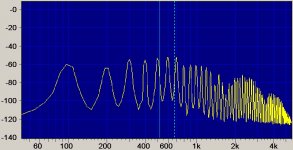
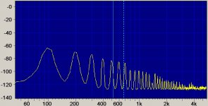
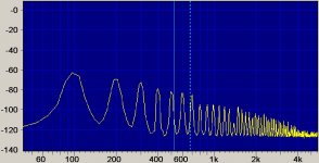
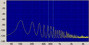
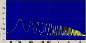
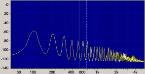
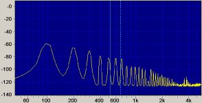
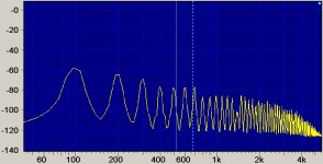
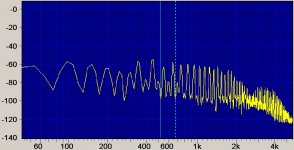
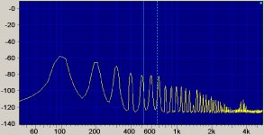
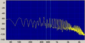
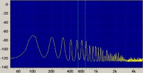
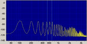
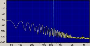
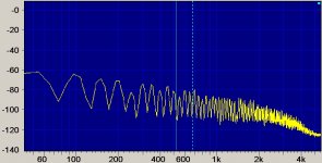
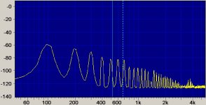
If you give me a little time, I could readapt that work to English. In that work, there are links to .wav files of how you would hear disturbances in a simple test amplifier.
There are also links of the spectrum images of these noises.
As soon as I can, I'll upload it.
Regards
If you give me a little time, I could readapt that work to English. In that work, there are links to .wav files of how you would hear disturbances in a simple test amplifier.
There are also links of the spectrum images of these noises.
As soon as I can, I'll upload it.
Regards
PD: unzip "Diferencias entre fuentes de alimentación.zip" and open "Silencio2.doc". Read carefully. Open audio file and play the .wav files in the indicated sequence. Later, open image file in the indicates sequence.
Attachments
-
Diferencias entre fuentes de alimentación.zip629.6 KB · Views: 62
-
 Caso 5.jpg206.5 KB · Views: 63
 -
 Caso 4 bis.jpg187 KB · Views: 67
 -
 Caso 4.jpg191.2 KB · Views: 62
 -
 Caso 3 bis.jpg185.8 KB · Views: 62
 -
 Caso 3.jpg202.6 KB · Views: 183
 -
 Caso 2 bis.jpg185.8 KB · Views: 186
 -
 Caso 2.jpg195.8 KB · Views: 191
 -
 Caso 1 bis.jpg189.6 KB · Views: 220
 -
 Caso 1.jpg203.3 KB · Views: 237
More attachments
Attachments
-
 Caso 10.jpg208.1 KB · Views: 65
 -
 Caso 9 bis.jpg186.3 KB · Views: 59
 -
 Caso 9.jpg202.9 KB · Views: 59
 -
 Caso 8 bis.jpg183.2 KB · Views: 65
 -
 Caso 8.jpg200.1 KB · Views: 63
 -
 Caso 7 bis.jpg187 KB · Views: 55
 -
 Caso 7.jpg204.9 KB · Views: 63
 -
 Caso 6 bis.jpg185.2 KB · Views: 69
 -
 Caso 6.jpg201.1 KB · Views: 57
 -
 Caso 5 bis.jpg187.8 KB · Views: 65
Last edited:
More attachments
Attachments
-
 Caso Especial 1 bis.jpg186.1 KB · Views: 68
 -
 Caso Especial 1.jpg194.1 KB · Views: 61
 -
 Caso 10 bis.jpg185.4 KB · Views: 57
 -
Caso 1.zip573.6 KB · Views: 66
-
Caso 2.zip534.2 KB · Views: 67
-
Caso 3.zip532.2 KB · Views: 59
-
Caso 4.zip503.8 KB · Views: 66
-
Caso 5.zip654.3 KB · Views: 71
-
Caso 6.zip330.9 KB · Views: 66
-
Caso 7.zip656.3 KB · Views: 60
Last edited:
More attachments
Attachments
-
Caso 8.zip278.4 KB · Views: 60
-
Caso 9.zip613 KB · Views: 60
-
Caso 10.zip613.3 KB · Views: 57
-
Caso 1 bis.zip534.2 KB · Views: 73
-
Caso 2 bis.zip534.5 KB · Views: 52
-
Caso 3 bis.zip488.7 KB · Views: 74
-
Caso 4 bis.zip489.2 KB · Views: 59
-
Caso 7 bis.zip465.2 KB · Views: 82
-
Caso 6 bis.zip556.4 KB · Views: 57
-
Caso 5 bis.zip549.3 KB · Views: 78
Last edited:
More attachments
Attachments
Last edited:
That the centre tapped can give rise to unequal currents in the two halves of the centre tapped winding and that this unequal current causes saturation of the transformer core leading to poorer performance.
can be true if the center tap is not exactly located,
it is for this reason that bifilar winding is used to wind secondaries
i use this in my power traffo builds, and four wires so that
each secondaries cab be used as dual bridge or
single bridge using a center tapped configuration.....
GAS Ampzilla is the first power amp that i know
of that used this technique in the 70's....
and the reasoning given was to avoid hum causing ground loops...
Diego, unless you at least compare one of the simulation outcomes with a real measurement then all your sim results are just that - sim results - with no verification.
There is also a lot to be gained in experience and appreciation of parasitic values by setting up a real, but simple circuit, and then tuning a simulation to get good correlation between waveform/spectrum results.
Once a simple circuit is well simulated, then any supplementary results based on, for example, parasitic value changes, can be easily simulated (as some changes can be onerous to insert without changing other aspects) and with a level of confidence that what they show is valid.
- Status
- Not open for further replies.
- Home
- Amplifiers
- Power Supplies
- Power supplies differences