Yep fair point but since Diego has something of substance to contribute, let's take a look. I for one would like to understand which circuit corresponds with each plot.
Diego do you have an index table to identify each circuit or configuration? What was the 'best' circuit? Looks like '09_bis'?
Diego do you have an index table to identify each circuit or configuration? What was the 'best' circuit? Looks like '09_bis'?
Last edited:
Both drawings in post17 are wrong.
Hi Andrew & other knowledgeable folks,
Did I fix the problem? Are the attached circuits correct?
Thx! Pops.
Attachments
Diego, unless you at least compare one of the simulation outcomes with a real measurement then all your sim results are just that - sim results - with no verification.
There is also a lot to be gained in experience and appreciation of parasitic values by setting up a real, but simple circuit, and then tuning a simulation to get good correlation between waveform/spectrum results.
Once a simple circuit is well simulated, then any supplementary results based on, for example, parasitic value changes, can be easily simulated (as some changes can be onerous to insert without changing other aspects) and with a level of confidence that what they show is valid.
That simulation work has been verified in practice. It has been decided to upload only the simulations, to avoid that the dispersions of a real circuit confuse the objectives that I wanted to show are obtained.
The images of the spectrum were averaged about 400 times, to suppress the instantaneous variations. In this way, I have tried to show the convergence of the results.
Regards
Yep fair point but since Diego has something of substance to contribute, let's take a look. I for one would like to understand which circuit corresponds with each plot.
Diego do you have an index table to identify each circuit or configuration? What was the 'best' circuit? Looks like '09_bis'?
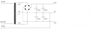
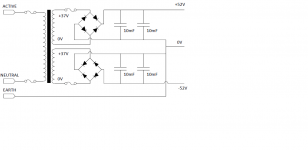
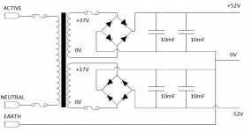
As I said, clearly the scheme in which the secondary is separated into two independent windings, is the one that best behaves against the changes cited in the work. It should be noted that two rectifier bridges should be used instead of one, apart from diagraming a strategic reference point (where there should be no load pulses from the main capacitors).
Regards
As I said, clearly the scheme in which the secondary is separated into two independent windings, is the one that best behaves against the changes cited in the work. It should be noted that two rectifier bridges should be used instead of one, apart from diagraming a strategic reference point (where there should be no load pulses from the main capacitors).
Diego - like this? 😉
I planned to use a 2mm copper bus plate to link all 8 capacitors (from both channels) to GND as shown for one channel in the attached png file.
Attachments

Last edited:
I planned to use a 2mm copper bus plate to link all 8 capacitors (from both channels) to GND
See plan attached (showing only single bridge per channnel). If dual-bridge configuration is better, then I need to find space for 4x integrated bridges on the bus-plate, which also serves as heatsink.
For symmetry I assumed a single GND connection would be in the centre of the bus-plate between the rectifiers (which are electrically isolated). From previous comments, it sounds like the rectifier 0V reference connection should be made at the other end of the bus - away from the Earth/GND. Or is the relative location of the rectifier & Earth/GND connection to such a lump of copper quite insensitive?
Thanks in advance. Pops.
Attachments

Last edited:
The rectifier connections are not for the purpose of establishing a reference voltage, but for the purpose of providing a path for charging current.popchops said:From previous comments, it sounds like the rectifier 0V reference connection should be made at the other end of the bus - away from the Earth/GND.
Only if you can find superconducting copper. All other copper has resistance, so develops voltage when current flows.popchops said:Or is the relative location of the rectifier & Earth/GND connection to such a lump of copper quite insensitive?
In my circuit, the charging loop for both + and - rail involves the 0V line. Is this correct or is this a mistake in the dual-bridge config? This is the question.
I can see that in the single rectifier config, the charging loop goes from pos rail to neg rail and back to the rectifier without touching GND (?). This cannot be so for the dual bridge where each pos/neg rail is isolated with separate rectifier. Where is the current return? 0V? Need to minimise resistance here with a bus bar to get maximum filtering effect hence the copper.
I can see that in the single rectifier config, the charging loop goes from pos rail to neg rail and back to the rectifier without touching GND (?). This cannot be so for the dual bridge where each pos/neg rail is isolated with separate rectifier. Where is the current return? 0V? Need to minimise resistance here with a bus bar to get maximum filtering effect hence the copper.
The 0V line is what emerges from the PSU at the clean end. Within the PSU you have charging pulses so what you call the '0V line' will not be at 0V with respect to the clean end. It probably does not matter too much whether you have a single '0V' bus or two joined at the clean end. If I were using two bridges I would probably use two '0V' lines.popchops said:In my circuit, the charging loop for both + and - rail involves the 0V line. Is this correct or is this a mistake in the dual-bridge config? This is the question.
In the single bridge version, the CT connection carries charging pulses too whenever the two polarities take different currents - which will be almost always.I can see that in the single rectifier config, the charging loop goes from pos rail to neg rail and back to the rectifier without touching GND (?). This cannot be so for the dual bridge where each pos/neg rail is isolated with separate rectifier. Where is the current return? 0V? Need to minimise resistance here with a bus bar to get maximum filtering effect hence the copper.
No need to minimise resistance (within reason). Much more important to connect things in the right order. Wire or normal PCB trace is fine.
Thanks DF96 - useful advice. How can you use two 0V lines? Each mono amp only needs -V, 0 and +V.It probably does not matter too much whether you have a single '0V' bus or two joined at the clean end. If I were using two bridges I would probably use two '0V' lines.
What is the right order? Thanks!Much more important to connect things in the right order.
Hi Pops, two mono amps in one chassis. It is all in the detail. Build two mono amps, each with its own transformer and power supply. Connect each amp GND to the chassis using a ground loop breaker and connect PE to chassis.
popchops, does your toroid PT have two separable wires coming from the secondary CT, or is the CT just one external wire with no way to internally separate (standard core transformers would typically bring the two internal winding wires to an exposed terminal, where it may be possible to separate them).
If you had two 'CT' wires available, then you could use a single bridge, and gain better charging current separation, by taking each separate CT wire directly to its related capacitor pad, as that would then effectively isolate those highest charging current pulses to just the first filter cap, and not to the common 0V ground plane that you are likely to use.
If you had two 'CT' wires available, then you could use a single bridge, and gain better charging current separation, by taking each separate CT wire directly to its related capacitor pad, as that would then effectively isolate those highest charging current pulses to just the first filter cap, and not to the common 0V ground plane that you are likely to use.
That simulation work has been verified in practice. It has been decided to upload only the simulations, to avoid that the dispersions of a real circuit confuse the objectives that I wanted to show are obtained.
Would you have a link to the real/sim comparison results and sim circuit? I think that would be of benefit to a few who are interested in the background tech details, and would likely allow better appreciation of the content of the multiple sim results.
Ciao, Tim
popchops, does your toroid PT have two separable wires coming from the secondary CT, or is the CT just one external wire with no way to internally separate.
Hi trobbins. I'm not sure what you mean. I have my eye on a pair of custom toroidal transformers, each with two 0-37V secondary windings. So at this stage anything is possible on that front.
If you had two 'CT' wires available, then you could use a single bridge, and gain better charging current separation, by taking each separate CT wire directly to its related capacitor pad ... and not to the common 0V ground plane that you are likely to use.
Hmmm I planned that each transformer would have 2x primary wires (0-240V) and four secondary wires (2x 0-37V). What is PT/CT?
I can't visualise what you mean. Are you just suggesting to ditch the copper ground plane? I'm open to that idea. Will definitely save space. Do you really mean 1 bridge per transformer?
Please please... take a moment to sketch what you are proposing. Sounds like it's worth understanding.
Cheers. Pops.
Hi Pops, two mono amps in one chassis. It is all in the detail. Build two mono amps, each with its own transformer and power supply. Connect each amp GND to the chassis using a ground loop breaker and connect PE to chassis.
Hi Mark! Yep I have one and a half Elektor Q-Watts. You say connect to chassis... is it correct that all GND connections should converge in one place? Is this star grounding? Is a ground loop breaker just a pair of diodes babk to back with a small capacitor parallel?
Please sketch if you have 5 mins... for me and all the other noobs. Cheers!
Would you have a link to the real/sim comparison results and sim circuit? I think that would be of benefit to a few who are interested in the background tech details, and would likely allow better appreciation of the content of the multiple sim results.
Ciao, Tim
Only what I can give is the link to the forum where I did it. About a week ago my hard drive was broken and I was not able to recover all the information, although much of that information is in that forum.
I tried to rescue everything that is in that forum for those who can not register.
Possibly, later, I can redo all measurements and oscillograms.
The secret is to avoid by all means that the charge pulses dirty the reference point of 0 volts (in other words, take another path).
Regards
PD: For all members: Have you been able to understand the document that I uploaded and compared the differences between the two schemes?
Last edited:
Sorry for acronyms.
PT = power transformer (as compared to OT = output transformer).
CT = centre tap, as commonly found in transformer secondaries with eg. a 37V-0-37V voltage rating, as compared to the equivalent transformer with secondaries 0-37V and 0-37V. In your post #42, the left schematic shows a CT connection going to 0V. That CT may be one wire coming from the transformer. In common laminated stamped core transformers that have terminals, the CT terminal can often be seen with two wires coming to it (one wire from each of the secondary windings). If so, then it may be possible to separate those two wires - to then effectively give two separate windings.
you have a single 240Vac primary (I suspect you actually have a 230Vac primary since that is the nominal voltage we have for our harmonised supply).Hi trobbins. I'm not sure what you mean. I have my eye on a pair of custom toroidal transformers, each with two 0-37V secondary windings. So at this stage anything is possible on that front.
Hmmm I planned that each transformer would have 2x primary wires (0-240V) and four secondary wires (2x 0-37V). What is PT/CT?
You have a dual 37Vac secondary.
Does the transformer have a label? Does it say 230Vac & 37Vac?
230:dual 35Vac is much more common.
I hardwire the rectifier circuit. The transformer to rectifier to first smoothing capacitor is the current charging circuit. That circuit passes charging current for ~10% duty cycle and must of necessity pass current peaks that exceed 6times the rms current seen at the load. If we add on a second stage of smoothing, then the current flows on a slightly longer duty cycle and the peaks are a bit lower when only 10milli-ohms of wire resistance intervene. More resistance (thinner wire) stretches the duty cycle and lowers the peak current.I can't visualise what you mean. Are you just suggesting to ditch the copper ground plane? I'm open to that idea. Will definitely save space. Do you really mean 1 bridge per transformer?
for a dual secondary I suggest you charge each smoothing cap bank from it's own rectifier. Then combine the outputs of multiple banks at the end most remote from the transformer.Please please... take a moment to sketch what you are proposing. Sounds like it's worth understanding.
Cheers. Pops.
Last edited:
I disagree.Hi Mark! Yep I have one and a half Elektor Q-Watts. You say connect to chassis... is it correct that all GND connections should converge in one place? Is this star grounding?
The star ground (I use the phrase Main Audio Ground (MAG)) is where all the separate circuits that need a common voltage reference converge. This star should not be part of other two wire circuit interconnections.
Resolve ALL the intermodule two wire interconnections first. Keep the current in one circuit SEPARATE from the current in other circuits.
When all the intermodule two wire connection are complete, then return to your schematic and find which voltage referencing connections are missing. Add in those missing connections.
The Main audio Ground is part of the audio system and is required to allow the amplifier to work. The amplifier does not need an enclosure/chassis to operate.Is a ground loop breaker just a pair of diodes babk to back with a small capacitor parallel?
Please sketch if you have 5 mins... for me and all the other noobs. Cheers!
But we have two rules that we should follow when building mains powered projects.
All ClassI equipment must have the Protective Earth wire directly and permanently connected to the Chassis. This is a Safety rule. It has absolutely NOTHING to do with getting the amplifier to work. That third wire in your mains cable, the yellow/green striped one, is the Protective Earth wire. Often referred to as PE.
If you don't have a metal chassis, then make the PE connection to the dominant metal part of the amplifier.
There is a second rule that we should follow:
All exposed conductive parts should be connected to the protected Chassis.
Again this is for Safety only. This too has NOTHING to do with getting the amplifier to work.
This rule is here just in case there is some catastophic failure inside the protected Chassis where a Live connection/wire comes into contact with some other internal conductive part. This failure could make some exposed external part Live. You must not touch that Live part during the period of the equpment being connected to the mains. Connecting all exposed conductive parts to chassis, protects your "touch" from killing you.
We can achieve this second part by physically connecting all metal parts directly to the chassis/enclosure. but some parts are intrisically connected to the audio system.
Instead we connect the Main Audio Ground of each channel to the Chassis. If you only have ONE channel (i.e. monoblock) then this Safety connection can be a robust wire that is capable of passing Fault Current to PE and thus blow the Mains Fuse. This Fault Current can exceed kA.
Where we have multiple channels inside the enclosure, then we find that making these multiple Safety connections can create current loops around which interference can circulate. For these we may obtain better interference performance by using a Disconnecting Network (DN) in the wire link to the enclosure. This DN must be able to pass Fault Current. This is the part that requires a Power Diode in both directions to conduct the Fault Current.
The Diode must survive longer than it takes for the mains fuse to rupture and the arc to extinguish. This is a very onerous condition.
I used a 25A/35A bridge rectifier wired in double parallel and asked if it was safe. This question remained untested/unanswered for a couple of years. Until I tested it. In my amateur way I concluded it was safe and reported my result. I have never seen any similar report by an other Member for this or any other style of DN.
Last edited:
One '0V' line connects the positive bridge to the negative ends of the positive supply caps; the other connects the other bridge to the positive ends of the negative supply caps. These two lines join at the PSU output. This arrangement keeps charging pulses for one polarity out of the PSU ground bus for the other polarity. Not a great advantage, but does no harm.popchops said:How can you use two 0V lines? Each mono amp only needs -V, 0 and +V.
Rectifier - reservoir cap - any other caps - PSU output - chassis (if appropriate)What is the right order?
- Status
- Not open for further replies.
- Home
- Amplifiers
- Power Supplies
- Power supplies differences