Hello
Could you please let me know what would be the differences between the 2 power supplies in the attached schematic?

Version 2 is working perfectly. the second transformer I plan to use, does not have the wire in the middle of secondary coil, so no GND connection from transformer, the GND will start from capacitors. as shown in the upper scheme. will this work at all?
Could you please let me know what would be the differences between the 2 power supplies in the attached schematic?
Version 2 is working perfectly. the second transformer I plan to use, does not have the wire in the middle of secondary coil, so no GND connection from transformer, the GND will start from capacitors. as shown in the upper scheme. will this work at all?
Could you please let me know what would be the differences between the 2 power supplies
in the attached schematic?
Version 1 can only give a single voltage. A center tap is necessary for a split supply in most cases.
TI has a 20mA virtual ground device for low power use. http://www.ti.com/lit/ds/symlink/tle2426-ep.pdf
If the drain on the two rails is not EXACTLY the same, the "ground" will be off-center, possibly all the way to one rail.
The drain on the two rails is never exact-same.
"Virtual ground" sometimes makes sense for low-power devices. But 6800uFd suggests this is quite a big system. The virtual-ground device becomes as big as the main output power devices.
Get a PT with a CT.
The drain on the two rails is never exact-same.
"Virtual ground" sometimes makes sense for low-power devices. But 6800uFd suggests this is quite a big system. The virtual-ground device becomes as big as the main output power devices.
Get a PT with a CT.
Both can work, all it means is that the source impedance of the rails will be higher with respect to ground.
Both can work, all it means is that the source impedance of the rails will be higher with respect to ground.
NO! It wiil *not* work. Even the slightest bias current will cause the center to drift towards either side.
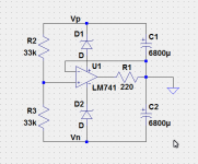
If the only current going to/from ground is bias currents - say from feedback networks - then the attached circuit should do the work. If Vp or Vn is > 15V, then add zeners to reduce the voltages for the op-amp.
Attachments
Common-mode noise due to the effect of signal currents on a finite source impedance will occur with any supply. It is a matter of degree. It takes a substantial supply to do without the centre tap but it can be done.
I forgot ...
.. In a power amplifier, the ground current can be rather substantial and if this happens and if the voltage rating of the capacitors are much less than Vcc+Vee, then there is a real risk that the one that sees the total voltage will explode!
And believe me, you do *not* want to sit close by! You may suffer real and serious injury!
As they say : don't try this at home.
No. You cannot draw DC through a capacitor. The first circuit will only work in the sense of being a single polarity supply (with a reservoir cap made from two caps in series which lack equalising resistors). The second circuit is a dual polarity supply, or a supply with a centre-tap - which is what I assume the OP wants.AllenB said:Both can work, all it means is that the source impedance of the rails will be higher with respect to ground.
thank you all for your help !!! after what i read i will just drop the idea of using capacitors to make a center rail. i have another idea though.
since I have a toroid with 2 secondary windings (2x35 V 600 VA) and four wires (35-0, 35-0). What do you think would work best connecting the 2 central cables of the 2 secondary windings of the transformer (maybe creating a center-tap so)and using one rectifier bridge. Or as shown in the scheme bellow 2 rectifiers, what will make me comfortable as the 2 rectifier will be sharing the peak load:

since I have a toroid with 2 secondary windings (2x35 V 600 VA) and four wires (35-0, 35-0). What do you think would work best connecting the 2 central cables of the 2 secondary windings of the transformer (maybe creating a center-tap so)and using one rectifier bridge. Or as shown in the scheme bellow 2 rectifiers, what will make me comfortable as the 2 rectifier will be sharing the peak load:
Peak load on each rectifier will be the same using 1 or 2 rectifiers. Average load will halve.
Ah didn't realize that. If only the constant load will be shared, might still benefit on terms of less heat, and maybe better working parameters with half load.
Any other benefit from using 2 rectifiers as in the scheme, or is it a complete non sense?
Sent from my iPad using Tapatalk
HI
i am a noob, but i think the tolerances of all the diodes at one half of AC could be a topic but i think you use the same type.
also thermic coupling is needed i guess.
Also look at the thickness of the wireing of L because of at the max current for loading the caps
....im hope its not non sense too😀
kr
chris
This supply method should be used with a resistive divider. I assumed this was implicit. My bad.No. You cannot draw DC through a capacitor. The first circuit will only work in the sense of being a single polarity supply (with a reservoir cap made from two caps in series which lack equalising resistors). The second circuit is a dual polarity supply, or a supply with a centre-tap - which is what I assume the OP wants.
Some people say that using two bridges is better. I can't remember why, and it would be only a small advantage anyway. Two bridges gives you a slightly smaller output voltage as you have more diode drops.
There is a body of opinion that the separated windings into the dual rectifier uses the transformer better.
That the centre tapped can give rise to unequal currents in the two halves of the centre tapped winding and that this unequal current causes saturation of the transformer core leading to poorer performance.
Some also claim that the dual rectifier is quieter than the centre tapped.
I have not seen any evidence for either of these two arguments and have not seen it in any of my builds. Maybe I don't do enough comparisons.
single or dual bridge
Evening all - I was going to ask exactly the same question.
Which of the following power supplies is better? Cost of a second rectifier is not much...
Clearly the second bridge is taking some of the load which must be a good thing during capacitor inrush? I did also read something about dual bridge being more robust in case of asymmetric load on the +/- rails, like at very low frequency maybe? Anybody fill in the blanks?
Except the cost and space and additional wiring - is there any downside risk here?
Also - pls just check I made no mistakes. Is each diagram technically viable? Thx!!
PS - Sorry the pictures are so small. VISIO fail!
Attachments


Last edited:
Those two both have the same fault: a ground connection to the charging pulse loop. In addition, the second one does not take advantage of the possibility of separating the two charging pulse loops - you can't do this with the first one.
Both diagrams are wrong.
I don't agree with any of this.Clearly the second bridge is taking some of the load which must be a good thing during capacitor inrush? I did also read something about dual bridge being more robust in case of asymmetric load on the +/- rails, like at very low frequency maybe?
Thanks for the responses.
Hmmm I was inspired by:
Solid State Power Amplifier Supply Part 1
This guy also seems to have the GND rail connected to both bridges.
Can anybody share a corrected, verified circuit that makes best use of the two bridge rectifiers?
And also - can anybody explain in physical terms what is the benefit of spending another £4.
Thanks for the support!
- Status
- Not open for further replies.
- Home
- Amplifiers
- Power Supplies
- Power supplies differences