I can't see nothing wrong
Totally agree with You...
I order this torrid today i think.
Jesper
Calculate PSU.
Calculate PSU.
Hello.
I am trying to calculate an appropiate psu size for this mini.
The PSU i use now, which is way to big, consist of 8x22000uf. The first 4x22000uF is reservoir, and the remaining 4x22000uf is on cap. bank after Resistors (CRC). - There are 5x0.47ohm (0.11ohm)(Both on + and - rails)
Calculating the "rolloff" giving me 1/(2*3.14*0.094*0.088) ~19Hz.
If i calculate an FirstWatt psu, with 8x15000uF, the calculation :
1/(2*3.14*0.11*0.060) ~24Hz.
I understand, that having this as near as "0" as possible is best, but the right
uF / R / uF giving a balance, where there is not too much dissipation on resistors and not crazy many uF is something which much be considered.
So quistion is :
1. Howto calculate the amount on uF on first bank ? (Dual mono psu's)
2. I see, that having a lot of uF after resistors, giving a better rolloff, is there a rule of thumb for this ?
3. Whats best practice of having rolloff 20, 30 40Hz., and how do it affect the amplifier
The rails are +19vdc / 0vdc(GND) / +19vdc
Bias is ~1,2A
Jesper.
either leave it as is , or try moving one "cell" of 22mF at amp side
no need for over-engineering that
dissipation through resistors will be practically always the same ( Iq dominating ) , but you can slightly ease burden of xformer and rectifiers
no need for over-engineering that
dissipation through resistors will be practically always the same ( Iq dominating ) , but you can slightly ease burden of xformer and rectifiers
either leave it as is , or try moving one "cell" of 22mF at amp side
no need for over-engineering that
dissipation through resistors will be practically always the same ( Iq dominating ) , but you can slightly ease burden of xformer and rectifiers
Hi ZM, and thanks for answering 🙂
I am in for making two new psu-boards (dualmono), and reason i ask quistion is that i would calculate the resevoir bank + cap. bank at amp. side.
I am reading all kind of stuff regarding the CRC pi filter, but if i ask quistions again, maybee you can help ?
I am also trying to figure out, why rolloff must be that low, and how it affects amp. (Can't find anything on net)
So quistion is :
1. Howto calculate the amount on uF on first bank ? (Dual mono psu's)
2. I see, that having a lot of uF after resistors, giving a better rolloff, is there a rule of thumb for this ?
3. Whats best practice of having rolloff 20, 30 40Hz., and how do it affect the amplifier
Jesper.
best to learn with Duncan's PSUD
I'm lazy ( besides being plain dumb) , but you can read some useful musings here , besides many other things on same page : FIRST WATT ARTICLES
as I said - do not over-engineer that ; however , your will to learn is good
I'm lazy ( besides being plain dumb) , but you can read some useful musings here , besides many other things on same page : FIRST WATT ARTICLES
as I said - do not over-engineer that ; however , your will to learn is good
best to learn with Duncan's PSUD
I'm lazy ( besides being plain dumb) , but you can read some useful musings here , besides many other things on same page : FIRST WATT ARTICLES
as I said - do not over-engineer that ; however , your will to learn is good
Thanks.
Will investigate further 🙂
Jesper.
Duncans psu
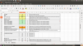
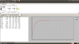
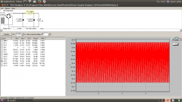
So trying to simulate, the psu i got now.
If i set load for current 250mA then output voltage is very near the real life setup.
But i guess 250mA is far from, what one channel AlephJ mini draws ?
EDIT :: Also attached with 500mA draw, then voltage drops way below real life setup.
Any explanation ?
Jesper.
Attachments

Last edited:
.....
Any explanation ?
Jesper.
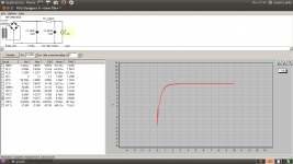
fiddle with xformer data
use F1 key to learn how to do that
also - caps impedance - read from datasheet ....... 2R is waaaaaay too much
fiddle with xformer data
use F1 key to learn how to do that
also - caps impedance - read from datasheet ....... 2R is waaaaaay too much
Cool...
Will do that!
Btw. : I just meassured with serial true-rms dmm = 1,3A (one channel)
Jesper.
Attachments
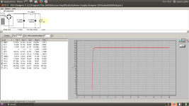

and question is ?
None 😀 ... Got them answered in Jumas thread...
Any comments on that psu!
Jesper.

Hi Jesper
Can low output bias can go for acceptable sound ? (For sissy heatsink) 😀
Don't know... how low ? I can try it!
Jesper.
600-1000mA ?
Hope you've got sensitive speakers or listen at low levels.
- Status
- Not open for further replies.
- Home
- Amplifiers
- Pass Labs
- AlephJ Mimi! (Mini)