Spookydd said: we've clipping early and at the input stages, and that's where the oscillations happen.
I guess this extra pair at the ltp eats up a little too much headroom, which makes the clipping happen there first.
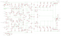
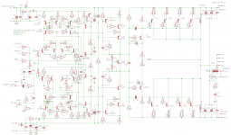
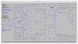
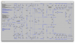
I say: Yep. My aim was to reduce high frequency distortion by cascoding the LTP, but the cascode bias is wrong. I'd just like to see the thing work and see if it does indeed move the curve. I think the symmetric cascode keeps things better balanced and will continue refining it.
A cascode bias adjustment may allow just enough headroom to avoid premature clipping. The base stoppers may reduce the tendency to ring.
I guess this extra pair at the ltp eats up a little too much headroom, which makes the clipping happen there first.
I say: Yep. My aim was to reduce high frequency distortion by cascoding the LTP, but the cascode bias is wrong. I'd just like to see the thing work and see if it does indeed move the curve. I think the symmetric cascode keeps things better balanced and will continue refining it.
A cascode bias adjustment may allow just enough headroom to avoid premature clipping. The base stoppers may reduce the tendency to ring.
Attachments
A cascode bias adjustment may allow just enough headroom to avoid premature clipping. The base stoppers may reduce the tendency to ring.
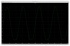
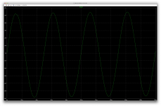
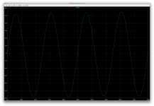
It's better, but still clips too early. It was starting to oscillate earlier before, and now it starts a little later, so it's better but not quite enough yet.
The oscillations only happen because it clips I think.
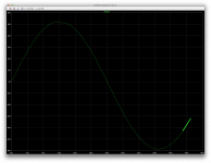
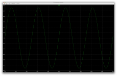
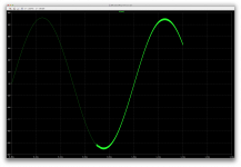
If I reduce the input level to 1.3V, as before, the clipping doesn't happen and it doesn't oscillate.
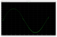
While at it, I added one more shot of the sine wave with the lower 1.3V input signal, which not only shows it's not oscillating, but shows that since I kept the delay cycles to 0 to see the signal from the very start, there is a very visible drift of the zero crossing, which demonstrate the need to wait for the amp to settle before looking at things properly.
And by the way, we see the early clipping only at the positive side and not at the negative, and curiously the start of the oscillations doesn't happen where it clips...
The reason for the clipping only at the positive side may just be related to that drift I mentioned, and after several cycles of settling time, it may start the clipping more symmetrically.
Attachments
Last edited:
Spookydd said: The oscillations only happen because it clips I think.
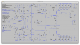
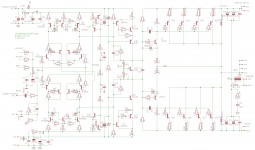
I say: Instead of clipping, I suspect the current mirrors are saturating. This is very bad. People propose various cures. I'm trying Schottky clamps.
I changed cascode bias pickoff point, unrelated to the mirror saturation. Self claims this yields lower distortion, so it seems better practice.
I say: Instead of clipping, I suspect the current mirrors are saturating. This is very bad. People propose various cures. I'm trying Schottky clamps.
I changed cascode bias pickoff point, unrelated to the mirror saturation. Self claims this yields lower distortion, so it seems better practice.
Attachments
I say: Instead of clipping, I suspect the current mirrors are saturating. This is very bad. People propose various cures. I'm trying Schottky clamps.
I changed cascode bias pickoff point, unrelated to the mirror saturation. Self claims this yields lower distortion, so it seems better practice.
We'll see about the lower disto when it works well.
Are you sure you have those diodes turned in the right direction at the top ltp mirror?
The vas bias went down a lot, cut by about half, so biasing the outputs took a little more doing, and we're having a much larger offset on the rail centering now.
Perhaps this may be related to how the diodes are turned, but this time we see what looks like clipping at the bottom instead. Although as you mentioned, this may not be actual clipping, but it does kind of looks like it.
I'll try turning those top diodes around to see what happens...
Attachments
Turning around those upper diodes puts things back to about normal.
The vas bias is back to about the same as previously, around 30-31mA, and the rail centering is back to real good.
Biasing the output also works again as earlier.
Obviously the diodes should be turned that way.
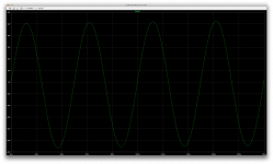
The input level at 1.35V as normal only allows the first cycle to show that odd clipping behavior, but since I'm not skipping early cycles, this can be attributed to the needed settling time.
I upped the delayed cycles back to my previous 10 and we can see the sine wave looks normal again and there is no apparent offset of the zero crossing, which obviously only happens early on and this is skipped by jumping over the first 10 cycles.
I will run more involved simulations now.
The vas bias is back to about the same as previously, around 30-31mA, and the rail centering is back to real good.
Biasing the output also works again as earlier.
Obviously the diodes should be turned that way.
The input level at 1.35V as normal only allows the first cycle to show that odd clipping behavior, but since I'm not skipping early cycles, this can be attributed to the needed settling time.
I upped the delayed cycles back to my previous 10 and we can see the sine wave looks normal again and there is no apparent offset of the zero crossing, which obviously only happens early on and this is skipped by jumping over the first 10 cycles.
I will run more involved simulations now.
Attachments
Well, trying to run more involved sims revealed oscillations.
At first it seemed fine when I ran it at 20hz, with the first 10 cycles skipped, as it would be done most of the time.
But when I tried running the stepped sim with 20,1k,10k and 20k frequencies, only the first part at 20 ran at normal speed, with the rest being super slow.
When it's that slow, oscillations are usually responsible, so I ran it at 20 only, to find it ran fine, but then at 1khz it's oscillating.
It take such a long time that I stopped it before it finished, and there is no point in running at higher frequencies until this is fixed.
Attachments

Interesting. We interpose a cascode, then the current mirror oscillates (I believe). This instability has possibly been masked by limitations of the LTP. It may not be productive to develop this further. I see quite a few caps and RCs here and there to bandaid this, which I dislike.
But if we roll back to a previous known working level, should we keep the Schottky clamps on the mirror? My inclination is to keep them.
Also, I changed the collector resistor on the input transistors for higher open loop gain/lower distortion. This may affect compensation.
But if we roll back to a previous known working level, should we keep the Schottky clamps on the mirror? My inclination is to keep them.
Also, I changed the collector resistor on the input transistors for higher open loop gain/lower distortion. This may affect compensation.
Attachments
But if we roll back to a previous known working level, should we keep the Schottky clamps on the mirror? My inclination is to keep them.
Well, I don't think they would do any harm, but I didn't feel the need before.
Also, I changed the collector resistor on the input transistors for higher open loop gain/lower distortion. This may affect compensation.
It is having a much harder time finding its operating point as it is now. It can take over a minute to get the op as opposed to a near instantaneous, or small fraction of a second usually. Perhaps the much higher res values at the ltp collectors may have something to do with it, and probably not the diodes.
It took a while to find the optimal adjustment for the wanted bias, due to the extra long time it takes to resolve.
Once this is done, the transient sim runs fine and I'm not seeing any hints of oscillation, so I felt no need to touch the compensation.
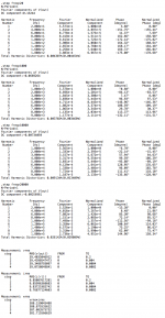
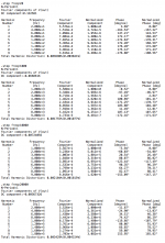
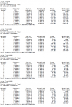
However, as you can see in the thd results, although it's mostly the same at the low end, it does rise sharply at the higher end, so something is amiss and insetad of bettering the thd, it's actually worsening it.
Can you imagine how much harder it is to design something without simulation?
We can try many things, quickly, and see what happens right away, which could never be done if designing strictly by calculations. You could only find out if calculations were right when building a prototype, and possibly blow something in the process. Simulation is great!
Attachments
Turns out, the diodes are causing this issue with finding the operating point quickly, and also they are causing thd to rise a lot at the higher frequencies.
I tried reducing the ltp collector resistor values to 4k7, to see what happens, and the time required to find the op was still very high, and thd was still rising sharply at the higher frequencies.
So then I returned the ltp collector res values to 10k and instead disconnected the diodes. And there it was, the op is found at normal speed, and thd doesn't rise much at hf.
The thd at the highest end is higher with 10k than before with 2k2 though.
So something isn't going in the expected direction.
Attachments

Spookydd said: {re Baker clamps on mirror} Well, I don't think they would do any harm, but I didn't feel the need before.
{and}
Can you imagine how much harder it is to design something without simulation?
I say: You are preaching to the converted. You also catch my goofs, such as the reversed Schottky's. We used to call this a design review; doctors say second opinion. All good. My regret is I can't do simple sims yet, and thus be able to try the small variations quickly. Regarding the baker clamps, they are possibly not needed, although Cordell recommends something similar, antiparallel diodes on the LTP. The idea is to prevent the mirror from ever saturating, it which case it would become a hindrance.
Before we abandon this change, I wonder if a smaller collector resistor such as 4.7k might work better, or if an even smaller one such as 1k. This collector resistor sets the gain and current through the input transistor, but also is base drive for the second transistor and thus the large value trashed HF operation.
I'm also curious about tweaking other parameters such as the LTP emitter resistors. The current value is 100 ohm, a compromise to ensure matching which trades away gain and adds a little noise. So, I will take you at your word, and suggest those paths.
Attachments
You also catch my goofs, such as the reversed Schottky's.
Well, that's the great thing about collaborating and sharing. More eyes are better than few.
All good.
Definitely!
My regret is I can't do simple sims yet, and thus be able to try the small variations quickly.
I think we can help you get your feet wet and get passed the initial blockage.
It's really not much to do. First you should grab ltspice, and then I can post a current set of files, so you can load them as is and let it rip without trying to figure it out. If I can hunt down every file that has to be included for the models, then it logically should work right out of the box for you without having to scratch your head. What do you think? Why not take the plunge? I bet that once you try it, you'll wonder how you could do without it until now.
Regarding the baker clamps, they are possibly not needed, although Cordell recommends something similar, antiparallel diodes on the LTP. The idea is to prevent the mirror from ever saturating, it which case it would become a hindrance.
They are apparently an issue there on the mirror, but maybe we can prevent the ltp from saturating and not worry about the mirrors. Byt putting those diodes on the ltp bases instead, which is likely what Cordell recommends, and I've seen this done by the likes of Bryston...
Before we abandon this change, I wonder if a smaller collector resistor such as 4.7k might work better, or if an even smaller one such as 1k. This collector resistor sets the gain and current through the input transistor, but also is base drive for the second transistor and thus the large value trashed HF operation.
Tried that, at least at 4k7, not lower than 2k2 as we've had earlier. I found that reducing from 10k to 4k7 didn't really change anything, although perhaps only a little less thd at the highest end with 4k7 instead of 10k.
I figured 2k2 was better. The thd difference is hardly noticeable except at 20khz, and with 4k7, it's only in the order of about 3ppm higher than with 2k2. It climbs a little more with 10k. So, counter intuitively, it gets worse with the higher values. The power of simulation. We find out quickly how wrong we are.
I'm also curious about tweaking other parameters such as the LTP emitter resistors. The current value is 100 ohm, a compromise to ensure matching which trades away gain and adds a little noise. So, I will take you at your word, and suggest those paths.
I can test a few values there to see which way it goes.
This isn't easy to do as a stepped simulation, because changing those values changes the operating point, which in turn requires other adjustments beyond the values themselves.
I did something like this with the mirror res values, but I had to seek proper bias adjustment value for each set of values, and switch with the stepping, which isn't very practical.
But for 2 or 3 values, I can adjust bias every time and re-run the sim. As long as only the bias is affected, it's not too bad. It would be a bother if compensation was different each time, but I doubt this is the case.
We have one good thing about our design right now: the needed miller cap value is low, which doesn't impose too much demand on the ltp to drive it, for decent slew rate, without having to drive the ltp too hard.
There is one more thing I was thinking though. Why even bother with trying to prevent saturation at the ltp and/or its mirrors? If we can drive the amp to full power before clipping, properly without any saturation, then we're fine, and all that I think we should have is a peak limiter to prevent the amp from clipping entirely.
Spookydd said: I can test a few values {of LTP emitter resistors} there to see which way it goes.
This isn't easy to do as a stepped simulation, because changing those values changes the operating point, which in turn requires other adjustments beyond the values themselves.
I say: Actually I only proposed 1 value in the schematic, 47 ohm. I don't want to get radical lest this blows up.
This isn't easy to do as a stepped simulation, because changing those values changes the operating point, which in turn requires other adjustments beyond the values themselves.
I say: Actually I only proposed 1 value in the schematic, 47 ohm. I don't want to get radical lest this blows up.
Actually I only proposed 1 value in the schematic, 47 ohm. I don't want to get radical lest this blows up.
I had not looked at the schematic details when I mentioned that.
What do you have in mind with making variable the collector res?
I kept the diodes disconnected for now, and with those collector res at 4k7 and the degen res reduced to 47, the operating point does take a while to be found, but I can see we have some oscillations, but not at 20hz.
The stepped sim with the 4 frequencies was taking such a long time, I stopped it and looked instead at 20 and 1k, with no skipped cycles, to see what's going on early on.
There aren't oscillations at 20hz, but they are there at 1k.
So perhaps the change of degen res values would require adjustments to the compensation to stop those oscillations.
I didn't try higher frequencies. It should work best at 1k anyway.
Attachments

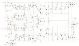
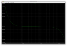
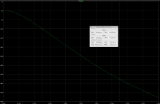
Here we are, with adjustments to the compensation, it works beautifully again, and even better now.
I haven't done noise sims or other juicy stuff yet, but the transient sim shows a nice result.
The delay cycles are back in, to skip the settling time, the miller caps down to 10p from 15p, and the global feedback comp cap down to 33p from 47p, which can not only reduce thd, but at the same time the smaller miller cap may improve slew rate a bit.
I'll try noise later on, and check on slew rate.
Attachments
...
What do you have in mind with making variable the collector res?
..with those collector res at 4k7 and the degen res reduced to 47, the operating point does take a while to be found, but I can see we have some oscillations, but not at 20hz.
...
There aren't oscillations at 20hz, but they are there at 1k.
So perhaps the change of degen res values would require adjustments to the compensation to stop those oscillations.
I didn't try higher frequencies. It should work best at 1k anyway.
Actually I suggest two tests. I put trim resistors to suggest trying a range of values, but realistically I am focused on only a couple of tests.
1 We know 2k2 collector loads works well. Freeze that. Test 47 ohm emitter resistors. This ~doubles gain and requires compensation changes. Goal is simply more open loop gain, to reduce distortion via NFB.
2 Revert to 100 emitter resistors. Test 1k collector loads. This reduces gain, may improve HF distortion by improving base drive to second transistor of LTP.
1 We know 2k2 collector loads works well. Freeze that. Test 47 ohm emitter resistors. This ~doubles gain and requires compensation changes. Goal is simply more open loop gain, to reduce distortion via NFB.
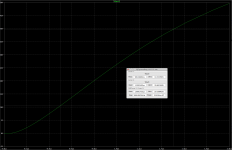
Looking good so far, and works as expected, for a change.
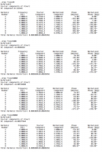
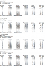
With 2k2 and 47, thd drops across the board, and it's even lower at 20k than at 20hz.
I'll take a peek at noise and slew rate, before trying the 100 and 1k.
Attachments
With 2k2 and 47, we have improvement with noise and slew rate a little as well.
I'll test with 100 and 1k now.
I'll test with 100 and 1k now.
Attachments

Spookydd said: Here we are, with adjustments to the compensation, it works beautifully again, and even better now.
..
... the miller caps down to 10p from 15p, and the global feedback comp cap down to 33p from 47p, which can not only reduce thd, but at the same time the smaller miller cap may improve slew rate a bit.
I'll try noise later on, and check on slew rate.
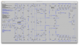
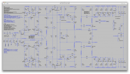
I say: Great. I see variables in your schematic but I cannot tell what values you chose. ??
I find it very interesting that not changing the topology, just changing parts values, can have this effect at this late stage. The initial component values chosen were safe starting points but not optimal. I assumed we were close to optimal values, but obviously there is room for improvement. Rather than me proposing changes via schematics, feel free to tweak this.
I'm reminded of operations research, in which optimums are chosen by finding points where the derivative of some function is zero, presumably at a peak or valley. But it could be a saddle, in which case you test by random walks to verify that the supposed peak is not a saddle. That is not directly applicable here, but perhaps the concept is, that is, to test that our design is optimal by varying component values within limits.
It seems we are using models only to analyze a design. It seems that it could be used to synthesize an optimal design, by using a generated range of component values. The variable component values could be chosen based on engineering judgement or formulae, but they could also be randomly generated automatically within limits and evaluated. I suspect that is already done in linear design labs.
My case in point is this latest variation of minutiae, the emitter resistors and collector loads. It turns out that slight changes can make dramatic improvements. I hope we are not overlooking other such cases.
..
... the miller caps down to 10p from 15p, and the global feedback comp cap down to 33p from 47p, which can not only reduce thd, but at the same time the smaller miller cap may improve slew rate a bit.
I'll try noise later on, and check on slew rate.
I say: Great. I see variables in your schematic but I cannot tell what values you chose. ??
I find it very interesting that not changing the topology, just changing parts values, can have this effect at this late stage. The initial component values chosen were safe starting points but not optimal. I assumed we were close to optimal values, but obviously there is room for improvement. Rather than me proposing changes via schematics, feel free to tweak this.
I'm reminded of operations research, in which optimums are chosen by finding points where the derivative of some function is zero, presumably at a peak or valley. But it could be a saddle, in which case you test by random walks to verify that the supposed peak is not a saddle. That is not directly applicable here, but perhaps the concept is, that is, to test that our design is optimal by varying component values within limits.
It seems we are using models only to analyze a design. It seems that it could be used to synthesize an optimal design, by using a generated range of component values. The variable component values could be chosen based on engineering judgement or formulae, but they could also be randomly generated automatically within limits and evaluated. I suspect that is already done in linear design labs.
My case in point is this latest variation of minutiae, the emitter resistors and collector loads. It turns out that slight changes can make dramatic improvements. I hope we are not overlooking other such cases.
Spookydd said:
With 2k2 and 47, we have improvement with noise and slew rate a little as well.
...
No real improvement with 1k and 100.
Lowering the degen res does help more.
I say: Good, and hopefully we maintain stability. The downside of reducing the emitter resistors is more sensitivity to poorly matched input transistors. But the upside seems to be lower noise and lower distortion. We may have to hand select these, since the makers are dropping matched pairs. I have a few in my parts drawers, but I can't use them for new design because the supply is uncertain.
As I said before, please tweak this yourself if you sense an opportunity for improvement. As for me, I would like to see what 1k/47 yields. Only at 20khz perhaps?
Is the VAS the next area?
- Status
- Not open for further replies.
- Home
- Amplifiers
- Solid State
- grounded collector amp